Thank you George; I've been there, done that. Mixed concrete with Poly-Vinyl-Acetate as well, it rings like a bell, compared to concrete with gravel of very random sizes, but I have to admit it flows well, and looks nice after curing.
For structural integrity I prefer rusted nails and screws.") And iron wire.
And iron wire.
For structural integrity I prefer rusted nails and screws.
And iron wire.Thanks a lot for all your precious comments. Any link to this German stuff ? Any idea about their foam ?There were some German table radios... It was to be seen inside good speakers (AR and maybe ADVENT) in the past. A variation of this was a diagonally hanged, twisted damping foil.
About the last quoted part, hard to find something new, in the audio world. And even if you believe it was a personal idea, how can be sure that it was not hidden somewhere in your reptilian brain ;-). The pleasure is in testing something different and find it improves something.
About A.R., those i knew at the time, where "Aerial suspension", damped in the entire volume to be adiabatic.( If i remember well ). I'm a little crossed against them, because they introduced the fashion of low efficiency closed boxes for decades...
Last edited:
Respect, mr.Wurcer, you can recognize your nice babies at first sight, even in very low resolution avatars. I'm impressed.
As i was with so many good sounding current feedback op amps from A.D. (They are many in my system)
Sad to see many of them disappear one after the other from catalogs with this mention :"Obsolete".
Those input FET's are a dead giveaway, I notice not recommended for new designs, oh well.
Those input FET's are a dead giveaway, I notice not recommended for new designs, oh well.
What are they recommending instead?
Alas, you cannot do that. The suspension ring has a more important function which is to keep the coil centred in the magnet gap. While the fibreglass can provide back/front stiffness, it cannot provide enough radial stiffness.To remove suspension ring, then reduces fractioning forces...
In most cases, you want less front/back stiffness rather than more. Stuffing the cavity with fibreglass can provide adiabatic conditions. The decrease in acoustic stiffness is limited to about 20% while true adiabatic conditions would give you 40%.
Density of fibreglass required is quite high. About that of a firm pillow or cushion. This is always good for sealed boxes.
It can also be designed into Reflex enclosures if you can allow a bit more volume but the parameters must be carefully chosen. The requirements for a big magnet are slightly relaxed though.
Mr Wurser, i'm very curious about those mysterious places, where all those integrated circuits where designed.
May i bore-you with few questions ?
Did-you build discrete prototypes before the IC ?
Did-you have good audio equipment to listen to your prototypes and first samples ?
If yes, what was the part of the listening and the measurements ?
Last question, did final Op Amps sounded very different from the original discrete prototype, if some ?
It was not about electromagnetic cones, but electrostatic compression drivers for horns.Alas, you cannot do that. The suspension ring has a more important function which is to keep the coil centred in the magnet gap. While the fibreglass can provide back/front stiffness, it cannot provide enough radial stiffness.
Mr Wurser, i'm very curious about those mysterious places, where all those integrated circuits where designed.
May i bore-you with few questions ?
Did-you build discrete prototypes before the IC ?
Did-you have good audio equipment to listen to your prototypes and first samples ?
If yes, what was the part of the listening and the measurements ?
Last question, did final Op Amps sounded very different from the original discrete prototype, if some ?
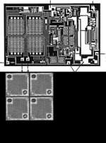
No, sorry to disappoint all sim only no audio listening. This part was done for spy sonar and CAT scanners.
Here is an interesting picture comparing it to 4 2SK170's.
Attachments
It was not about electromagnetic cones, but electrostatic compression drivers for horns.
The constant charge electrostatic speaker (the only one which has advantages over Rice & Kellog's invention in certain applications) doesn't really benefit from this. It's low impedance is already a good match to air. Moving coils are high impedance so gain from the transformer action of a good horn.There were some German table radios from 1955-1965 that had small round (~30-50mm Dia) electrostatics, the construction of which fits exactly to your description. They worked fine (and the foam does not rust-disintegrate-after all these years)
But a more recent application of the principle you describe is piezo film units sold by Pioneer in the late 70s, early 80s. These were very different from the Motorola units used by Dalquist etc which were just piezo bimorphs driving a cone.
I have to say, these are IMHO, just toys. I've looked at a lot of ways of making a noise and done a lot of theoretical work on some too. Only 2 methods have the potential for 'good sound'. Moving coil direct radiator speakers and constant charge electrostatics. There are good reasons why R&K is dominant from tiny transistor radios to High End. It is the only principle that allows a single unit to cover 20-20kHz and more importantly, sound like it does so and sound good too ... not that such a unit is easy
Last edited:
I used to work on two other designs in the 70s: Orthophase, ( http://img43.xooimage.com/files/4/5/2/orthophaserw4-205f678.jpg) and film with a similar magnetic circuit (a magnetic version of electrostatic. Both are better for less fractioning than cone, both suffered from low efficiency, and no way to go down to 30Hz with orthophase ...Only 2 methods have the potential for 'good sound'. Moving coil direct radiator speakers and constant charge electrostatics
I agree with you for cones at low frequencies, not much at medium and hight (It need further nuances). reason why i am interested, on a pure intellectual point of view, to imagine a 2" compression driver with decreased distortion and increased bandwidth to high frequencies. let say from 500 to 20 000.
Mr Wurcer, yes, i'm disappointed, in a way.
Was-it the same @ Maxims and Harris ? No listening ?
I still have those big PMI,& AD databooks... Christmas...
I used to work on two other designs in the 70s: Orthophase, ( http://img43.xooimage.com/files/4/5/2/orthophaserw4-205f678.jpg) and film with a similar magnetic circuit (a magnetic version of electrostatic. Both are better for less fractioning than cone, both suffered from low efficiency, and no way to go down to 30Hz with orthophase ...
I agree with you for cones at low frequencies, not much at medium and hight (It need further nuances). reason why i am interested, on a pure intellectual point of view, to imagine a 2" compression driver with decreased distortion and increased bandwidth to high frequencies. let say from 500 to 20 000.
Mr Wurcer, yes, i'm disappointed, in a way.
Was-it the same @ Maxims and Harris ? No listening ?
I still have those big PMI,& AD databooks... Christmas...
There have been brief attempts to introduce audio criteria, beyond the common parameters shared by many disciplines, within the development of integrated circuits. One could argue that some of them were simply misguided.
But PMI did make a serious gesture in that direction. I know little of the details, but one of their promotions was an ad campaign which featured little ditties about how one might be an Audio Silicon Specialist.
Needless to say, few missed the implication that, as such, they would be an A&S.
Last edited:
Our version was called the Isodynamic so this is a principle I've done extensive theoretical & practical studies.I used to work on two other designs in the 70s: Orthophase, ( http://img43.xooimage.com/files/4/5/2/orthophaserw4-205f678.jpg) and film with a similar magnetic circuit (a magnetic version of electrostatic. Both are better for less fractioning than cone, both suffered from low efficiency, and no way to go down to 30Hz with orthophase ...
I agree with you for cones at low frequencies, not much at medium and hight (It need further nuances). reason why i am interested, on a pure intellectual point of view, to imagine a 2" compression driver with decreased distortion and increased bandwidth to high frequencies. let say from 500 to 20 000.
The limits are not in efficiency. In the 70's magnet materials would have been a practical problem. Planar speakers (including electrostatics) obey similar Size/Efficiency/Bass eqns as cone speakers in boxes. This was first realised by Rice & Kellog and formalised by Garner & Jackson.
The bigger Magnepans go down to 30Hz but I believe some of them are only single sided unlike the push-pull Isodynamic (and Orthophase I think) so aren't accurate transducers in my book.
A real problem with planar speakers is the supporting frame precludes the very best mid & treble performance. This holds even for the ESL63.
On horns, I must side with R&K ... but for your compression driver, distortion is determined mainly by the compression ratio. So use the least amount for your required efficiency. Also less drastic horn flares. Exponential flares though they give the most 'extended' bass are also the worse for distortion.
A simple conical horn, though 'bass' is limited has practically no 'horn' distortion and can be shaped to improve HF too. These days with sophisticated xover design and even DSP, the 'bass' response is not a problem. In fact the popular 'wave guides' around many treble units in box speakers today can be considered crude horns.
I have to say I design domestic speakers though I've done some head banging stuff like 16Hz at high level for organs.
The problem was the distance between the film and the magnetic source (if symmetrical, the large gap), and, as it was, for Orthophases units, the magnetic gap, due to the moving tolerance. It was a flat membrane with suspension on two opposite edges only. So, no box allowed, low impedance, (great number of // units needed for >4 ohms). More about them found here: Le forum Audio Vintage • Afficher le sujet - Système OrthophaseThe limits are not in efficiency. In the 70's magnet materials would have been a practical problem. Planar speakers (including electrostatics) obey similar Size/Efficiency/Bass eqns as cone speakers in boxes
About horn expansion curves, i stay stuck with the Delamare's formula. Did-you know the J.M. Lecleach's work ?
Not to forget Dr. Heil's (AMT), ribon speakers and amusing attempts like Ionovac etc...
Richard, there are formulas in the textbooks predicting horn throat distortion. The 3 important parameters are: area of throat at the beginning of the horn, horn cutoff frequency (determined by the rate of flare, primarily) and the acoustical output at the horn throat. This gives an equation that is proportional to frequency, inversely proportional to horn cut off, and proportional to the area of the throat at the beginning of the horn, and to the square root of the sound intensity (in acoustic watts)
or: second harmonic distortion=1.73 f/f(c) sq.rt I(t)times 1/100
f = driving frequency
f(c)= cutoff frequency (of horn)
I(t)= intensity in watts per square meter at the throat of the horn
Page 275 'Acoustics' Beranek
Also: "Equation is shown is nearly correct for finite horns because most of the distortion occurs near the throat." Beranek p. 275
See I told you, Dimitri, that these textbooks can come in handy! This cite comes from the one you bought me at AES some years ago.
John, I have the book. And, several others like it. what about what I said?
Let me put the question another way --- without a throat, there cannot be distortion from a throat. Doesn;t that mean horns are inherently bound to make more distortion than a non-horn (direct drive)?
The only advantage is the efficiency of horns. Obviously, distortion from the same driver putting out the same spl with and without a horn is different. But, that isnt the same thing as a horn generating distortion because of the throat size. Something a non-horn is free from.
In a home situation, adequate spl is rarely a problem. Now, for mid and high frequencies, the shape of the horn in controlling the directivity is quit useful, even in the home to minimize wall reflections, for example. Otherwise, I see no advantage to horns in a home.... especially if they are going to increase distortion.
Last edited:
Horns come to speakers from gramophones. It happened historically: gramophones did not use arrays, otherwise we would see development of arrays since beginning of the 20'th century, because obviously J.B.Lansing would use arrays for his speakers for theaters of moving pictures.
- Status
- Not open for further replies.
- Home
- Member Areas
- The Lounge
- John Curl's Blowtorch preamplifier part II