There was a vacuum photodiode with a GR connector on it that used to put out a fast pulse when suitably illuminated with a laser. I wonder how that compares to some of these other approaches.
Interesting, I have a friend here who worked with femto-sec laser pulses which can have very strange properties.
Whaaaa!?!?!
 ARGHHHHHhhhhh.....BANG!
(Puts bullet in own head to end the pain...)
Howard Hoyt
Dir. of Engineering
AMI, LLC
www.ami-media.com
We B Discs...
Could you improve the resolution of the photographic plates by running a green highlighter pen around the edge?
ARGHHHHHhhhhh.....BANG!(Puts bullet in own head to end the pain...)
Howard Hoyt
Dir. of Engineering
AMI, LLC
www.ami-media.com
We B Discs...
No, but they would sound better when they brokeCould you improve the resolution of the photographic plates by running a green highlighter pen around the edge?
Reminds me of a story. When the late Lawrence Aller decided that he was going to do more observational astronomy fairly late in his life, he fairly terrorized Lick Observatory with his errrr... practices. He was doing some image-intensifier-tube astrophotography and spectroscopy, and the particular image tube arrangement accepted a small rectangular photographic plate, a non-stocked size. So it was necessary to use a plate cutter in the darkroom to trim a piece off of a standard plate.
Aller had difficulties with the plate cutter, so he devised another method. When the night assistant went into the darkroom to clean up he found shards of broken plates all over the floor. Aller had smashed a plate and then felt around for one about the right size to fit in the plateholder
I'm also good at finding lost golf (goof) balls.
Coincidentally, I just spent the last three days at a golf ball factory near your former Mass digs. To quote Pico and Alvarado, "They're all around us Sergeant, they live here!"
In the hands of some people that could get turned into a "physicists/astronomers/educated people etc. - what do they know about real equipment?" generalisation.bcarso said:Reminds me of a story. . . .
Could we all stand for two minutes in memory of Howard? I didn't realise that he has a deep phobia about anything green.
The difficulty we have is that people who appear not to understand 'higher level math' still feel free to offer their opinions on its inapplicability to audio. (One could argue that Fourier is not higher level math anyway.) Responding to them can lead us further into the maths and they get even further out of their depth but they don't always realise this and we are sometimes too polite to say so at the time.
Sorry slow on catching up.
Yesterday I did a nice long lunch with a friend who teaches at a local semi-prestigious University. He also is a musician who occasionally plays with the local symphony. His area of expertise is acoustics, DSP etc.
I mentioned the bit about folks considering music and noise to be continuous as per Fourier. His response was "That's just silly." We went on a bit about what are the important bits about analyzing music and why particular methods don't work.
I also showed him my bits about capacitor and resistor distortion. He had no trouble following the simple math or the conclusions.
He then discussed a problem he was encountering in some other research. As it really was classified he could not go into detail, but there were some issues in common with stadium sound so those details we could go over without my gaining any insight into his project.
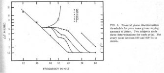
He also filled me in a bit about the 10usec arrival discrimination bit and how it is used at low frequencies and stops working around 1,000 hz.
A nice long lunch with a colleague who does work in the field although on quite different issues and has lots of useful knowledge related to what I do.
Either you misrepresented what we are saying or he does not understand Fourier. You choose.simon7000 said:I mentioned the bit about folks considering music and noise to be continuous as per Fourier. His response was "That's just silly."
Either you misrepresented what we are saying or he does not understand Fourier. You choose.
No we understand it. Everybody who does gets a chuckle out of your assertions.
See http://en.wikipedia.org/wiki/Periodic_function
Last edited:
He also filled me in a bit about the 10usec arrival discrimination bit and how it is used at low frequencies and stops working around 1,000 hz.
Stops working around 1k??
I guess you could make the assumptions that everything above 1k is not jittered by cone movement due to lf content, and I guess one could also assume that there are no other pressure wavefronts below 1k to modulate zero crossings the cilia respond to..
jn
Attachments
Last edited:
Stops working around 1k??
I guess you could make the assumptions that everything above 1k is not jittered by cone movement due to lf content, and I guess one could also assume that there are no other pressure wavefronts below 1k to modulate zero crossings the cilia respond to..
jn
That's one method of localization, then others come into play. The interesting issues was when HF is modulated by LF.
His suggestion was to play tones into a pair of headphones and use a phase adjustment on one ear. Above 1K the shifting goes away. I haven't tried it but if you get a different result I certainly will. That would make for another interesting lunch.
John spelling corrected during cross posting!
Last edited:
Perhaps you could briefly state what it is you believe I and others are asserting, which you disbelieve and your friends find amusing.simon7000 said:No we understand it. Everybody who does gets a chuckle out of your assertions.
As I recall this issue arose from your claim of 'distortion' arising from a first-order CR filter, because the output signal looks different from the input signal so you believe it contains new frequency components (or, perhaps, that the concept of frequency components is false/unhelpful in this context)..
You are welcome.
If you ever decide to persue this, let me know, I'll assist if you wish.
My first resistors used simple clad perfboard, but I've also used 1/8th copper with drilled holes in a hexagonal array for packing density. Recently aquired an x/y/rotary machining stage for my wooden gear clock stuff, it would be perfect for drilling an array of holes into copper. Once the resistors are soldered, the whole kittenkaboodle can be epoxied to a heatsink form using stycast thermal epoxy, that'll get back the sum of the dissipation rating.
Since I have published this in the public domain, there are no costs associated with IP.
Oh btw. The best I've ever measured is 250 pH, I cannot reliably measure below that. If I need to do so, I'd have to toss a 250 pSec step into it and look for overshoot. 250 picoseconds is how fast a mercury wetted relay lets go. 350 on make. (IIRC, could be t'other way round, it's been 31 years.)
jn
Here is another treatment of the issue with good illustrations:http://www.newtons4th.com/wp-content/uploads/2010/03/APP012-Current-Shunt-Field-Cancellation.pdf
You can buy commercial variations on the concept-AC Current Shunt, Alternating Current Shunt, Precision Current Measurement http://support.fluke.com/calibration-sales/Download/Asset/3381946_6203_ENG_B_W.PDF
There are a few others also used in cal labs.
No we understand it. Everybody who does gets a chuckle out of your assertions.
See Periodic function - Wikipedia, the free encyclopedia
Appeal to experts now? That IS silly. DF96, I suggest you give up until Ed can address the issues on his own.
Last edited:
The one method of localization, then others come into play. The interesting issues was when HF is modulated by LF.
The one method of localization?? You have lost me.
His suggestion was to play tones into a pair of headphones and use a phase adjustment on one ear. Above 1K the shifting goes away. I haven't tried it but if you get a different result I certainly will. That would make for another interesting lunch.[/QUOTE]
I have an even better idea.
Get two turntables (technics direct drive SL 51's work the best).
Get two 12 inch singles of the same song.
Get a nice mixer.
Get a reasonable headphone, stereo of course.
Synch both songs, run program in your left ear, run cue in your right ear.
Now, set the intermix slider in the middle.
Take one turntable, and slow it down/speed it up so that the image YOU hear in the headphones slides from right to left, left to right. YOU will hear all the musical content drifting from one side to the other.
Your customers on the dance floor will hear a phasing/flanging effect.
Oddly enough, your friend hasn't gotten out much, eh? I was doing this in a nightclub back in 1978. Still have the vinyl as well as the tables and mixer. Just recently sold two 18 inch PAS speakers and gave away two PAS 15's in a cab with a pair of D205TI tweets..
To prove my point in striking fashion, get two copies of Freddy James "Get on up and boogie" or France Jolie's "Come to me", the cymbals were recorded VERY hot on both, although they are albums, not 12 inch singles. Yet, the cymbals still slide from side to side during phasing/flanging.
jn
Perhaps you could briefly state what it is you believe I and others are asserting, which you disbelieve and your friends find amusing.
As I recall this issue arose from your claim of 'distortion' arising from a first-order CR filter, because the output signal looks different from the input signal so you believe it contains new frequency components (or, perhaps, that the concept of frequency components is false/unhelpful in this context)..
A first order CR filter increases distortion by reducing the level of the fundamental even on periodic signals is one issue.
A non periodic signal that does not have a derivative that is similar to itself will also distort. A sin has cosine so there is only phase shift in those cases.
Noise and music are non-periodic so they cannot be reduced to a Fourier series.
Let me know what you don't understand.
Last edited:
I have an even better idea.
Get two turntables (technics direct drive SL 51's work the best).
Get two 12 inch singles of the same song.
Get a nice mixer.
Get a reasonable headphone, stereo of course.
Synch both songs, run program in your left ear, run cue in your right ear.
Now, set the intermix slider in the middle.
Take one turntable, and slow it down/speed it up so that the image YOU hear in the headphones slides from right to left, left to right. YOU will hear all the musical content drifting from one side to the other.
Your customers on the dance floor will hear a phasing/flanging effect.
Oddly enough, your friend hasn't gotten out much, eh? I was doing this in a nightclub back in 1978. Still have the vinyl as well as the tables and mixer. Just recently sold two 18 inch PAS speakers and gave away two PAS 15's in a cab with a pair of D205TI tweets..
To prove my point in striking fashion, get two copies of Freddy James "Get on up and boogie" or France Jolie's "Come to me", the cymbals were recorded VERY hot on both, although they are albums, not 12 inch singles. Yet, the cymbals still slide from side to side during phasing/flanging.
jn
John,
That is known as Flanging because it was originally done with phase locked tape players and by changing the drag on just one you got the effect. We are not talking about those issues. I suspect that getting the records out of sync by 10 usec would be really difficult! More delay of course changes the image location!
We are just talking about one part of stereo localization.
Although at lunch we did diss Sirius radio as it has too many of those artifacts!
Here is another treatment of the issue with good illustrations:http://www.newtons4th.com/wp-content/uploads/2010/03/APP012-Current-Shunt-Field-Cancellation.pdf
You can buy commercial variations on the concept-AC Current Shunt, Alternating Current Shunt, Precision Current Measurement http://support.fluke.com/calibration-sales/Download/Asset/3381946_6203_ENG_B_W.PDF
There are a few others also used in cal labs.
Nice info, thanks.
The newton4 method is what I designed back in '81 for my TRR rig. I splayed 10 Be0 10 ohm resistors in a radial pattern on the 1/4 thick copper plate.
The second is a design from NIST, they sold rights. The interesting thing was, they made a large array of resistors just like I did, but they did NOT fold the current back through the array for total cancellation. As a result, they absolutely must keep symmetry in their voltage pickup. Too close to the current leads and there is a leading edge overshoot, too far and the risetime is too slow.
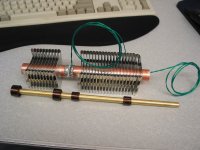
The third, fluke, is like the resistor I made back a ways, it was coaxial by design...pic attached. If you look carefully, it was a b##ch to build. I abandoned it because the coaxial tube structure still had inherent inductance, it's just that the field was confined to the space between tubes. And yah, it's slant fin.. The tube with the four kapton tape rollups is the building/centering fixture. It kept the two tubes axially correct during soldering.
The second and third designs will moniter current very well, but they still will have insertion inductance, it's the B dot component of the measurement leads that they zero'd.
ps..I have that nist paper somewhere in my office, buried..sigh
jn
Attachments
Last edited:
Appeal to experts now? That IS silly. DF96, I suggest you give up until Ed can address the issues on his own.
No lunch with a friend and telling funny stories. Then I come across DF beating his chest!
- Status
- Not open for further replies.
- Home
- Member Areas
- The Lounge
- John Curl's Blowtorch preamplifier part II