But odds are if enough people say something matters, then it does and you wont be adding in unnecessary expense. That does happen a lot in high-end.
Except if all of the people who "say something matters" belong to the same group of internet forums or read the same publications dedicated to the topic and convince each other. Throw in a few predatory snake oil vendors to add some fuel to the fire.
To be fair, I didn't believe this at first, then I found Head-Fi and Audio Asylum.
With that rationale, we should all be buying $5000 silver AC power cables. There are thousands of audiophiles on the internet that have heard great improvements from replacing their power cables, surely it must be true.
It is needed a lot of "art" to made an amplifier, able e.g. to invert phase of one harmonics of input signal and so dramatically change shape of signal, while preserving the same amplitude of spectral components..The ear is sensitive to waveform shape, amoungst other things, and knowing the average level of a harmonic does not correlate to what might have been heard because of this fact. just a point to be made about measuring harmonic levels in design of Audio amps.
So now we have four scenarios by which distortion is made more complex, and they can all be experienced with an ordinary audio amplifier. We have seen that these complex distortions can be concentrated into intense peaks, far more powerful than the average values that we might measure with a voltmeter.
Quoted from this paper, worth a reread:
Audio, distortion and feedback
A good assesment of the situation, and you would provide his 20% content.If only life were that simple! If someone is abusing the academic system then there is a good chance he will abuse his staff too. Integrity tends to be indivisible. Also, if he spends so much time at conferences who is running the department - his staff (he gets paid, they do the work).
I'm sure you know exactly that the author is methaphorically speaking.Who measures distortion spectra with a voltmeter?
If not, I suggest you should read the whole article, I gave the link.
Apart that, with a good signal generator, notch filters and a RMS voltmeter, it's perfectly possible to go through the harmonics.
As I learned here, there are no other harmonics than at frequencies as multiple, addition or subtraction etc. of the fundamental(s)
Quite time consuming though....
So "voltmeter" doesn't mean "voltmeter." Perhaps "distortion" doesn't mean "distortion?"
Yes, I've read it before. That's where I got the phrase "entertainment industry." Truly the most profound description of high end audio I've ever encountered, one more of many reasons why I respect Nelson more than just about anyone else in that marketing segment.
Yes, I've read it before. That's where I got the phrase "entertainment industry." Truly the most profound description of high end audio I've ever encountered, one more of many reasons why I respect Nelson more than just about anyone else in that marketing segment.
Robert Greene told me that understanding mathematics is lost on his students today because computers will do the calculations for you and thus no one derives anything anymore. Maybe same with semiconductors -- dont need to understand the physics of devices... with sim software and all.
But even in pcb layout with high speed digital... you need to know some things from analog.... like the higher harmonics travel on the outer edge of the trace and affect impedances for waveform fidelity etal. yet, even that has been characrterized in software.
Its a Plug-n-Play world (?)
Hving simsoftware is not a bad thing, the signalintegrity and power delivery system analysis software (though not used enough in PCB design) helps lay out a complex board that will work. When you have 14+ layers, thousnads of pins and connections all running at silly speeds you cannot work it all out manually, so the sim tools and 3D feild solvers do the donkey work for me, allowing me to optimise the layout by using the results of the sim tools. I also have to understand how a signal travels from one point to another, I belive it is necessary for todays complex designs, but I do seem to be in a minority (though this does keep me in work). I see the sim tools and computers that they run on as tools that have evolved over the years to allow me to do my job.
[...]Yes, I've read it before. That's where I got the phrase "entertainment industry." Truly the most profound description of high end audio I've ever encountered, one more of many reasons why I respect Nelson more than just about anyone else in that marketing segment.
Seeing his articles mainly as a marketing instrument may detract from the factual content.
Hving simsoftware is not a bad thing, the signalintegrity and power delivery system analysis software (though not used enough in PCB design) helps lay out a complex board that will work. When you have 14+ layers, thousnads of pins and connections all running at silly speeds you cannot work it all out manually, so the sim tools and 3D feild solvers do the donkey work for me, allowing me to optimise the layout by using the results of the sim tools. I also have to understand how a signal travels from one point to another, I belive it is necessary for todays complex designs, but I do seem to be in a minority (though this does keep me in work). I see the sim tools and computers that they run on as tools that have evolved over the years to allow me to do my job.
In the crazy high-speed world of telecom, we often have 10-12 Gb/s signals running around in 100 Gb/s systems (10 lanes, OTL 4.10). These signals run on 18-layer boards made of moderately exotic material like Panasonic Megtron-6. These boards are almost 0.1 inch thick and we must worry about what a via stub does to the signal. A trace near the component side of the board may have a via stub on the order of 80 mils. Sometimes the via stub is drilled out in critical applications. This is both highly analog in nature AND in need of sophisticated simulation tools.
The skin depth of copper at 12 GHz is about 0.5 micron. The microscopic smoothness of the copper on the interconnect layers even matters, as little mountains whose hieght is on the order of the skin depth can drastically increase the effective length of the trace at HF due to the skin effect (the signal has to climb the mountain and go back down). These traces are usually only 4-6 mils wide.
We also must use so-called "anti-pads" on the other layers through which the vias for these differential pairs pass. Most people have used an oval anti-pad that encapsulates the two vias of the differential pads. However, sophisticated simulations have revealed that the shape of the anti-pad wants to be rectangular for better results (the distance from the via to the edge of the anti-pad is more random with a rectangular anti-pad).
So, the problems at high frequencies in digital systems are very analog in nature and also needing of simulation tools.
Cheers,
Bob
thats why we need the sim tools and why PCB designers sleep badly.
HDI PCB design helps as you can have via in pad Removes the via stub) and can control the layers a via stack traverses and no back drilling.
For anyone interestedhere is a link to a handbook on HDI PCB design:
The HDI Handbook
Or have a look at the Wurth site:
Microvia HDI
We are doing more of these designs, quite often driven by component size as well as speed requirements (0.4mm 0.5mm pitch BGA's)
Seeing his articles mainly as a marketing instrument may detract from the factual content.
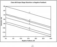
The Baxandall-test that shows added harmonics with increasing feedback is an interesting one, but has several perspectives.
The shown graph has been obtained from a single, non-linear device (a (j)FET).
However, if you look at a complete amplifier, the situation is completely different. Bob Cordell (hi Bob!) has done this test and got the attached result - you will see that there are NO additional harmonics generated by increasing feedback. ALL harmonics monotonously decrease with increasing feedback.
It also, except for some minor ripples, nicely illustrates what the theory says: put in x dB of feedback and the distortion gets divided by x. Neat, huh?
So, things are not always what they seem - which, of course, makes it all the more interesting
")
jan
Attachments
Last edited:
WOW!In the crazy high-speed world of telecom, we often have 10-12 Gb/s signals running around in 100 Gb/s systems (10 lanes, OTL 4.10). These signals run on 18-layer boards made of moderately exotic material like Panasonic Megtron-6. These boards are almost 0.1 inch thick and we must worry about what a via stub does to the signal. A trace near the component side of the board may have a via stub on the order of 80 mils. Sometimes the via stub is drilled out in critical applications. This is both highly analog in nature AND in need of sophisticated simulation tools.
The skin depth of copper at 12 GHz is about 0.5 micron. The microscopic smoothness of the copper on the interconnect layers even matters, as little mountains whose hieght is on the order of the skin depth can drastically increase the effective length of the trace at HF due to the skin effect (the signal has to climb the mountain and go back down). These traces are usually only 4-6 mils wide.
We also must use so-called "anti-pads" on the other layers through which the vias for these differential pairs pass. Most people have used an oval anti-pad that encapsulates the two vias of the differential pads. However, sophisticated simulations have revealed that the shape of the anti-pad wants to be rectangular for better results (the distance from the via to the edge of the anti-pad is more random with a rectangular anti-pad).
So, the problems at high frequencies in digital systems are very analog in nature and also needing of simulation tools.
Cheers,
Bob


[...]However, if you look at a complete amplifier, the situation is completely different. Bob Cordell (hi Bob!) has done this test and got the attached result - you will see that there are NO additional harmonics generated by increasing feedback. ALL harmonics monotonously decrease with increasing feedback.
[...]
Indeed interesting or even contradictory.
But the title of the graph you posted says "Class AB Output Stage Distortion vs Negative Feedback". So the title is misleading and these are the results of a complete amp?
http://www.ticertechnologies.com/tech_papers/05_CopperSurfaceLoss.pdf
also why for GHzs design cant use FR4 based laminates, the changing Er due to the fibres buggers up the signal as well, hence the more exotic materials such as Rogers 3200. There is a lot more to PCB's these days in higher end design, emebdded active devices is another area that is developing, the chip is mounted onto pads and embedded within the PCB, look for PDF:
Industrial PCB development using embedded
passive & active discrete chips focused on process and DfR
Done emebedded passives for a very high G system, the forces and vibration caused components to drop off, not what you want from the controlling electronics, but not done active devices yet.
I rarely talk with Nelson Pass, but I do respect him as a competitor. I first met him back in the late '70's at a hi fi store, that went badly, mostly because I got drunk and disorderly, thinking I was at a party, rather than doing business. That was the night that I turned down Harold Beverage at Benihana in SF, when he refused to consider changing the ceramic cap in the high pass filter in front of his amp driving his speaker.
We have even had some tension between us, when my office mate, Brian Cheney, asked me to make a BIGGER and (better) power supply for Nelson's preamp. I thought it to be a 'make-work' project at the time, because I had just been cut off by Lineage (Saul Marantz) in 1977, due to a cash crisis created by the stock market crash that year, and I had lots of bills to pay, many generated by Lineage.
In any case, I built an 'improved' power supply that could be substituted for the standard power supply, just by swapping a plug.
Then at the CES in early 1978, Gordon Holt was visiting the VMPS room and Brian called me over to hear the 'difference' between the 'new' vs the 'standard' supply. I thought:'sure, why not?' not expecting much. After all the 'standard' power supply was engineered OK, if a bit 'skimpy' but the real regulation was in the preamp, itself, much like the JC-80, so we were pretty remote from the audio, itself.
What Gordon Holt and I heard was a REVELATION to me! There really was a difference, AND we could go back and forth and hear it easily. Gordon Holt was so impressed that he BOUGHT Brian's power supply to put on his own preamp, and Brian Cheney asked me to make a second one for him. If this was all there was to it, then the situation would dissipate, but it did not go away. Gordon Holt decided to give Nelson Pass's preamp a really high rating ONLY if MY supply was used. What a dilemma! I wasn't set up to make these power supplies efficiently, they were just 'one offs' from my existing stock of components in my lab. Now I was getting orders. But that was not all! Nelson's people wrote a letter to 'Stereophile' saying that their 'standard' power supply was all that was needed. What a problem. However, public pressure finally got Nelson's group make an 'improved' supply so the demand was eventually met.
Now, I did this project in all innocence, not expecting much change due to my supply, and THERE IT WAS!. However, I was NOT off the hook. Brian Cheney reminded me that MY Vendetta SCP-2 external power supply was almost as 'marginal' as Nelson's, and so I had to make MY supply bigger too. This became the SCP-2A, and I have never regretted it.
This is a major approach in HOW we learn to make the best audio possible, over the decades.
Indeed interesting or even contradictory.
But the title of the graph you posted says "Class AB Output Stage Distortion vs Negative Feedback". So the title is misleading and these are the results of a complete amp?
I think those are the results for a complete amp. Nelson's results are similar to Baxendall's, they deal with a smooth non-linearity, lowish gain device, and low amounts of feedback. Boyk and Sussman have a paper (I think it's a free download on James Boyk's web site) that gives an extended mathematical treatment of several cases. This stuff is applicable to Nelson's as simple as possible FET amps. There are classes of amplifiers as Bob shows where this does not apply, it's not contradictory at all it's just not a universal principle.
Last edited:
Done emebedded passives for a very high G system, the forces and vibration caused components to drop off, not what you want from the controlling electronics, but not done active devices yet.
We've played with chip on board, even a 12 channel 10G amplifier (evil aspect ratio).
- Status
- Not open for further replies.
- Home
- Member Areas
- The Lounge
- John Curl's Blowtorch preamplifier part II