Work is fun..it has always been fun...
Those embedded in this discussion already understand terminology such as ESR and ESL.
And, it is important to stretch one's understanding. Questions are not wrong.
Think of e/m theory as a crossword puzzle.
j
ps...Is "ESL" considered polysyllabic??
O K E. S. L. not esselle. (As if that means much!)
There are folks that English is not the first words they used. (Names don't count.)
It was from Ads that I sent out to food store folks, that I found small words worked well. It can be hard to write with just monosyllabic phrases.
What I did learn is that for restauranteurs pictures worked best!
ES
Just like double blind tests need to be properly interpreted. '-)
Can't be too skeptical.
Thanks again, Ed Simon, for doing the test and putting up pictures here, of what you found.
It is a matter of anticipatory design practice that I decided to NOT use a center tap in the CTC Blowtorch, however, it is not always possible to avoid using a center tap. Then what? What about an air core inductor (5mH or so) in series with the center tap before it is connected to common?
Thank You for the info!
My interest is in not just the low frequency noise shown here but a more broadband approach. It is nice to note he did begin to understand that effective source resistance has a large influence on noise.
I answered to John, but hoped that Ed would rear it and comment. ")
I have a scope. And when I short tip of the probe with it's ground crocodile near any wire that charges caps through diodes I see spikes.
Ed, how long was the lead and the braid once they were separated and how were they dressed wrt to the circuitry under test? A photo would be nice, but probably too late for that.
3" I'll try to include a pretty picture in the article. Of course all circuits were tested the same as quickly as possible to insure the source noise stayed the same.
I did have a video guy once try to spec audio wiring. He wanted at least 5" of shielded twisted pair stripped back and covered with heat shrink tubing, using a green piece for the drain lead.
John (N) couldn't have explained it to that guy, not even with pictures.
My interest is in not just the low frequency noise shown here but a more broadband approach. It is nice to note he did begin to understand that effective source resistance has a large influence on noise.
An easier way to do it is what Morgan Jones and I have done- put 20 or 30 of them in series and feed them from a current source. The noise is then much easier to measure, and by dividing by sqrt n, the individual noise density can be obtained.
I answered to John, but hoped that Ed would rear it and comment.
Actually I thought I had nice diode switching pictures, but when I went to add them to the article I couldn't find them. So on my things to do list is to redo them.
I do have the "Magic" diodes that Digikey used to sell that have switching noise of 3 to 10 times the AC voltage. It was the introduction of these diodes that made just about everyone aware of diode noise. The manufacturer pointed out that noise was not a specified parameter and their diodes did meet all spec.s Of course they did fix their process. But once the superstitious folks found one bad source of diodes they went all out with diode fixes, even using them on quiet diodes.
Now I have enough pictures of the current through the rectifier diodes to show that the transformer voltage float extends the charging time to at least 30 degrees. As you know charging starts when the AC line goes above the stored charge. What is interesting is that the current demands are so high that the upward slope is compressed a bit. Then when the AC voltage begins to drop, the current demands drop also so the voltage drifts up to extend the charging time.
What this means is that the start of charging has a maximum surge current and the stop of charging is at a very low current.
So it is the turn ON noise that has more energy than the turn off! This goes against most folks theories of how to reduce diode noise. So a small resistor in series with the diode does a lot of good for noise reduction. A small inductor causes spikes like Steve Eddy wouldn't believe (At least not without pictures!)
So Wavey did I cover what you want to reveal to the uninitiated unworthies?
An easier way to do it is what Morgan Jones and I have done- put 20 or 30 of them in series and feed them from a current source. The noise is then much easier to measure, and by dividing by sqrt n, the individual noise density can be obtained.
Yes series works, but there are two assumptions that I don't think hold!
One is that diode noise is uniform diode to diode.
The second is that it is uncorrelated!
Now we get into a gray area of I.P.
Let me see if I can get permission to go a bit further.
I purchased 1000 feet of mike cable from parts express, and pull the braid off as I need it.
What do you do with the rest of the cable bits?
se
Morgan verified that the noise added by power. He got a bit of excess noise which he attributed to a questionable solder joint. And yes, the result will be an average.
I would consider an unverified bad solder joint explanation sloppy work. It might hide something interesting.
As is I assume obvious, the higher the current the lower the dynamic resistance and the lower the noise.
Or it could be a sloppy solder joint. It made very little difference to the predicted outcome, but Morgan likes everything nice and tidy, so a few percent difference bothers him more than it does me. You can read about it when the new edition of his book FINALLY appears. I just seriesed them, took the spectrum, divided by sqrt n, and called it a day- 0.4nV/rt Hz is way and away quiet enough.
It made very little difference to the predicted outcome, but Morgan likes everything nice and tidy, so a few percent difference bothers him more than it does me. You can read about it when the new edition of his book FINALLY appears. I just seriesed them, took the spectrum, divided by sqrt n, and called it a day- 0.4nV/rt Hz is way and away quiet enough.I cheat McMaster-Carr
Or Mouser, or DigiKey, or...
But to buy 1,000 feet of microphone cable in order to scavenge the shield?
I hope there's more to the story.
se
It would depend on the environment of the audio cable. High fields, high differential pickup. It's not rocket science..I did have a video guy once try to spec audio wiring. He wanted at least 5" of shielded twisted pair stripped back and covered with heat shrink tubing, using a green piece for the drain lead.
John (N) couldn't have explained it to that guy, not even with pictures.
Actually I thought I had nice diode switching pictures, but when I went to add them to the article I couldn't find them. So on my things to do list is to redo them.
Sorry, can't help you there. I used to do mil trr testing, built a rig to do 250 picosecond falltimes..good for sub nanosec diodes. But that's with a former employer.
The manufacturer pointed out that noise was not a specified parameter and their diodes did meet all spec.s Of course they did fix their process.
Some product does have speed limit, but in general, they only test for a recovery time maximum.
So it is the turn ON noise that has more energy than the turn off!
Inductively correct, but that energy is stored at a slew rate defined by the circuit resistance, source impedance, stray capacitances, distance to primary source impedance and the physical inductance of the feed wiring. During turn off, the diode will let go based on it's diffusion profile, recombination site density, sweep speed, local parasitic inductances and capacitances. The coupling to external circuits will depend entirely on the current slew rate, while locally it will be the IR drop effect and dI/dL. Turn on will in general, affect anything attached or very close. Turn off can radiate like a B....
toss em. I don't need white or blue wire. Magenta perhaps I would keep....What do you do with the rest of the cable bits?
se
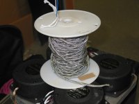
Here's a spool of braid over the core wires...the bass shakers are to precondition the electrons within the grain boundaries..
j
Attachments
Last edited:
Or Mouser, or DigiKey, or...
But to buy 1,000 feet of microphone cable in order to scavenge the shield?
I hope there's more to the story.
se
Oh, you didn't ask about that.
I purchased the spool to run mike's and unbalanced runs for a show in an auditorium. Used about 300 feet for that. Plus about 10 various and assorted mike cables, most about 50 feet.. The rest is on the spool at home...minus of course, what I use for play projects.
j
So Wavey did I cover what you want to reveal to the uninitiated unworthies?
No, I meant inductive pickup of magnetic field by shorted probes.
Oh, you didn't ask about that.
I purchased the spool to run mike's and unbalanced runs for a show in an auditorium. Used about 300 feet for that. Plus about 10 various and assorted mike cables, most about 50 feet.. The rest is on the spool at home...minus of course, what I use for play projects.
Ah, gotcha! I feel much better now. Thanks!
se
- Status
- Not open for further replies.
- Home
- Member Areas
- The Lounge
- John Curl's Blowtorch preamplifier part II