Good Idea Wavebourn, but is the plastic stick also conductive enough to be an RF barrier?
What RF through single 3 mm hole in 5 mm front panel?
OK, this is how I see it now:
I should go out of my way to put in an LED that will indicate that the preamp is on, when it is on 24 hrs/day, and has no on/off switch.
I should probably use a pretty BLUE LED, because they are very 'alluring'. Then I will be criticized for putting in a pretty LED, because it is more expensive than a cheap RED LED.
Have I gotten this right?
Last edited:
Not much, I am sure, but NO hole is even better.
As I said, it is the matter of preference. I believe Leonardo and Aivazovsky used different brushes and paints, so what?
Please elaborate .It is attached, actually. But attachment is modulated with 120 times per second speed. It is the matter of preference.
A 3mm aperture would still have some 30dB of shielding effectiveness at 1Ghz...
The key frequencies are 2.4 GHz, 5.8 GHz and the other ISM bands that have real activity as well as the Cell phone bands.
Its not difficult to put an effective screen across the hole. Or do it the Apple way with "translucent" aluminum (laser drilled very tiny holes): Getting The Details Right: Apple @ GRAFIKDOTCOM
I think a power indicator can be very helpful when you may have a problem. Much cheaper that shipping the box back because the power cord was not all the way in.
What RF through single 3 mm hole in 5 mm front panel?
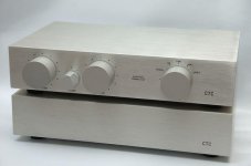
It is a big issue, you should have understood. But all of that insulated connectors at the rear panel with bare unshielded wires leading from them to switches, volume control, PCBs are fine and bring no problem with EMI/RFI throughput into the 'shielded' box
 .
.
I think a power indicator can be very helpful when you may have a problem. Much cheaper that shipping the box back because the power cord was not all the way in.
An "innovation" Harman implemented for powered speakers moved the coupling capacitor to the left satellite, allowing d.c. to be provided for an LED in the sat. Remarkable how much that reduced the frequency of product returns for the complaint "no sound out of left speaker".
A system is flanking my computer monitor as I type.
No, not really. You seem to be exaggerating a minor point.john curl said:I should go out of my way to . . . Have I gotten this right?
All this talk of hole size wrt wavelength partly misses the point. We don't have a hole, we have a hole plus wire poking almost through the hole. Inside the cage there will be a rapidly decaying (evanescent?) field from the hole, but it doesn't become zero imediately. Poke a conductor into that space immediately behind the hole and you can sample the EM field just outside the cage. To make a good Faraday cage you need small holes (wrt wavelength) and nothing inside the cage too near a hole. A regular array of holes is called a diffraction grating, so you could get effects which depend on exactly which direction you hold your phone.
A plastic light tube would probably be fine, unless it acted as a dielectric resonator. Isolating the wires would work - chokes or feedthrough capacitors. Making the circuitry itself relatively RFI immune would also help. I think it is unlikely that adding a panel LED to a well-designed circuit will seriously damage the sound. If it does, then the circuit needed better EMC performance anyway so the LED was a useful diagnostic tool.
3 mm is approximately 1/20 wavelength of 5.8 GHz. I have chassis made of perforated aluminium, full of such holes. Still, no radio reception.
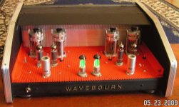
Likewise. Quite a few classic and excellent amps even have tubes on top of the chassis.
Then again, I don't use my cell phone while doing critical listening, its presence next to my left ear unbalances the imaging.
We don't have a hole, we have a hole plus wire poking almost through the hole. Inside the cage there will be a rapidly decaying (evanescent?) field from the hole, but it doesn't become zero imediately.
But he has INSULATED I/O connectors on the rear panel with all those cables going "through the hole" inside the preamp and this is fine??
You guys are exaggerating problems that do not exist and overlooking obvious issues, this is so usual in audio design.
But he has INSULATED I/O connectors on the rear panel with all those cables going "through the hole" inside the preamp and this is fine??
You guys are exaggerating problems that do not exist and overlooking obvious issues, this is so usual in audio design.
Thanks PMA , a simple search of PMA as the author and "connnector" as the subject brought me a whole new world to ponder...
dennis h
![ctc blowtorch open[1]-2.jpg](/community/data/attachments/270/270906-21a2cb21e6a92839feb3d55663fdef9a.jpg)
What I am being 'criticized' for not adding an LED. '-)
No, your questionable reasoning was criticized, not you.
No, just explaining why an LED in a high RFI environment apparently giving rise to audio problems does not mean that LEDs damage sound but it could mean that the wires to the LED are breaching the screen. This is to correct two opposing views:PMA said:You guys are exaggerating problems that do not exist and overlooking obvious issues, this is so usual in audio design.
1. LEDs damage sound. (No they don't, but the wires might if there is poor EMC performance elsewhere in the circuit.)
2. A panel LED can't possibly damage the sound. (True for the LED itself, but it needs wires and they might have an effect.)
I agree that it is likely to be a small problem.
Of course, other wires might cause problems too but we are not talking about other wires.
Of course, other wires might cause problems too but we are not talking about other wires.
It would be nice to distinguish between important and unimportant issues. As usually, unimportant 'issues' attract much more attention than necessary and important issues are not discussed.
- Status
- Not open for further replies.
- Home
- Member Areas
- The Lounge
- John Curl's Blowtorch preamplifier part II