Hello Gerhard,
As they say, beauty is in the eye of the beholder. I see nothing wrong with KA-8. It flies by the forces of nature and one can not fool these with some marketing tricks... Have you tried it?
No, I couldn't because I was in the "wrong" club, but we had one on our airfield and
sooner or later I will. I had some experience on the Bergfalke B & C, which is about
as beautiful but double seated and also harmless.
")
And no, I did not try to bend the forces of nature with marketing tricks, in the air my ar.. depends on it, and that would not be high end but simply end.
Gerhard
(writing this on semi-installed Linux Mint 12)
Last edited:
Any moderatly trained eye will tell you that Q9 base voltage is the sum of the diodes losses + Vce SAT Q9 + 1/2 tail current x R1.
I suppose you mean Vce sat Q14, but it's still incorrect, nobody is forcing Q14 in saturation (as long as you use a beta enhancer or degenerate the VAS). Give it a second thought and you'll find out you're chasing your tail in defining the beta enhancer bias current. Then read the old thread I've quoted, your attempt to solve an insoluble problem (in this approach) was discussed in extenso. You'll also find there Edmond's correct solution (a common mode control loop, shortly CMCL), a solution otherwise widely used in IC designs since the 80's.
A last comment about your design: without VAS current protection, it won't survive for long. It's a ticking bomb, waiting for the first heavy overload. Just another example of facts that simulations are not whispering into your ear.
I'm no longer gonna argue about, egos are already running to high here... Good night.
No, I couldn't <snip>
sooner or later I will. <snip>
Respect! I always was too "chicken" to go up in the air. I'll stick with wind and water.
Sorry for the OT stuff, folks, I'll stop now
Best,
.
A last comment about your design: without VAS current protection, it won't survive for long. It's a ticking bomb, waiting for the first heavy overload. Just another example of facts that simulations are not whispering into your ear.
I'm no longer gonna argue about, egos are already running to high here... Good night.
You have nothing to argue about since you re making a wrong
assumption about the VAS max current that show that you re unable
to analyze a circuit accurately...
Since the VAS is cascoded and degenerated by a 100R resistor
the VAS max current is about 35mA , largely within the VAS
thermal dissipation capabilities...
Yes, my mistake. The feedback network resistors should be much higher if they are directly loading the VAS.The feedback loop(s) are loading the VAS with about 550ohm...
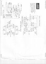
This design was predated by the phono stage of the Levinson JC-2, and before that, a hybrid design by Dick Burwen for Analog Devices in about 1966.
This is a simplified version, or what I called a 'kernel' at the time, to simplify the series thru-path and get a good slew rate. Both the jfet pair and the complementary bipolar quad that were used were American based, because the Japanese had not yet introduced their more exotic devices to the USA at the time (1977), in fact they may just have been on the drawing board.
This is a simplified version, or what I called a 'kernel' at the time, to simplify the series thru-path and get a good slew rate. Both the jfet pair and the complementary bipolar quad that were used were American based, because the Japanese had not yet introduced their more exotic devices to the USA at the time (1977), in fact they may just have been on the drawing board.
Last edited:
Now, what is the 'advantage' of this sort of circuit over a good IC, especially at the time that it was first used? (1977)
First, the circuit has to operate Class A, so it removes any crossover distortion.
Second, the circuit is fast, perhaps 50-100V/uS, because the additional compensation is minimum, to make it stable.
Third, it can be very quiet, especially with the later offered Toshiba jfet pairs.
Fourth, it has a MINIMUM thru-path between input and output, and virtually no input bias current.
etc.
Now, what are its limitations? Without a cascode on the input stage, the design works best between +/- 15V to 20V.
The device CANNOT drive a 600 ohm load, because the peak current only 5 ma or so, and the open loop gain will drop drastically with a load less than 2K ohm or so.
The layout takes somewhat more room than a typical op amp.
Still, this is one of the best 'compromises' that I have come across, and properly utilized, it will sonically 'beat' just about every IC op amp that is out there.
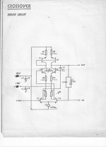
This is a 35 year old design that was originally made for the Symmetry Xover.
John,
What is Symmetry? I haven't heard that name before, except you mentioning it a few times? Is it some company or was it a code name for one of your projects?
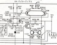
Why I'm asking? Take a look at this gain block from crossover by (now giant) Japanese company that hit the market around 1978. The similarity is stunning. Unless you were working for them, that's ....
Best,
Attachments
I do not specifically know this manufacturer...
John,
It's a SONY !
That gain module is from their top of the line crossovers TA-D88 and TA-D900.
Sony TA-D88B on thevintageknob.org
Sony TA-D900 on thevintageknob.org
I studied a lot of Japanese amp and preamp designs in the early '80's. We used to have "Musen to Jikken" and "Denpakagaku"(?) magazines going back to 1977 or so in our library at the company I was working for. Those mags published many schematics of comercial offerings, including exotic ones. Some of them used interesting, not seen before topologies. I always wondered who were the designers of these and thought that there must be some very good engineering potential and some very clever guys over there whose names we probably will never know.
Fast forward 30 years. Thanks to the internet and the amount of information available, I'm beginning to think otherwise. The picture becomes clearer now and small pieces of puzzle one by one snap into their places. I can certainly see now where one or the other manufacturer "got inspired" in the process of creating their own products. Hmm...
It is difficult to say where each design came from. I was somewhat surprised on the similarity of the Sony schematic to my own, but we may have derived it from the same place, which was the Levinson JC-2 phono stage 1973-76, published in 'The Audio Amateur' by me, in 1977, once my royalties were arbitrarily cut off. However, it could have been completely independently developed as well. It is a rather trivial execution of a fundamental design 'subcircuit' that has been used by many sources, both professional and amateur.
What I am trying to get across here is WHY I develop circuitry with this approach. I am fundamentally trying make circuits that 'sound good' not necessarily circuits that 'measure' good, even though I get both, most of the time. Yet, I am NOT trying to make a circuit 'sound' a particular way, but basically to NOT have a sound. If you can get the electronics 'out of the way' so to speak, then with 'luck' and a good musical source, you can sometimes achieve moments where 'you are there' at a performance that may have actually happened 50 years ago, for example. This is my goal.
To do this, an audio stage has to be extremely linear at working levels, reasonably to very quiet, depending on its location in the chain, fast, have an extended low and high frequency bandwidth, and virtually very low, or no easily measurable higher order harmonics. Some secondary considerations are more subtle, like high open loop bandwidth, and open loop DC stability, due to inherent symmetry of the circuit operation. These cannot yet be easily 'proved' but you can't argue me to ignore them.
I may have left something out, but that is pretty much all there is to it. The rest is just technology, parts quality and availability, construction and shielding, etc.
To me it is 'obvious' from years of experience that this is the way to go with solid state design. Yet, many here will disagree. Why they disagree is debatable. Some will accuse me of 'fooling myself' and others into believing that there are actual sonic differences in any 'reasonably well designed' circuit that measures well, and will attempt to force me into double-blind testing, that will invariably give null results, due to factors not well understood. Well, to each, his own.
What I am trying to get across here is WHY I develop circuitry with this approach. I am fundamentally trying make circuits that 'sound good' not necessarily circuits that 'measure' good, even though I get both, most of the time. Yet, I am NOT trying to make a circuit 'sound' a particular way, but basically to NOT have a sound. If you can get the electronics 'out of the way' so to speak, then with 'luck' and a good musical source, you can sometimes achieve moments where 'you are there' at a performance that may have actually happened 50 years ago, for example. This is my goal.
To do this, an audio stage has to be extremely linear at working levels, reasonably to very quiet, depending on its location in the chain, fast, have an extended low and high frequency bandwidth, and virtually very low, or no easily measurable higher order harmonics. Some secondary considerations are more subtle, like high open loop bandwidth, and open loop DC stability, due to inherent symmetry of the circuit operation. These cannot yet be easily 'proved' but you can't argue me to ignore them.
I may have left something out, but that is pretty much all there is to it. The rest is just technology, parts quality and availability, construction and shielding, etc.
Hi John,
Thank you for the concise summary of your design philosophy.
I, for one, view your approach with high regard. Though being a self-educated electronics technician I have no design skills, my limited background in electronics and my limited experience with "High End" audio systems lead me to appreciate your approach and philosophy as being commendable.
You seem to omitted in the above description "shortest possible signal path" and "no capacitors in the signal path, as long as it's possible".
To me it is 'obvious' from years of experience that this is the way to go with solid state design.
It looks to me that most of the above, save symmetry and perhaps extended low frequency bandwidth, applies also to tubes design.
What I am trying to get across here is WHY I develop circuitry with this approach.
John, you can do pictures now you are unstopable.
About time.
Well, might be a good idea, with Scott saying that the time is running out. We're all gonna die! But...that's always been true. meh!
As for shortest signal path, I like the idea of components sticking out both sides of the board, if indeed a board is used (vertically mounted or distanced from the chassis proper).
Some of those older 'holdover' designs were quite decent sounding, due to such execution. Although few ventured into the dual siding of through-hole components, which is probably the last bastion of perfection, outside of no boards at all.
remember solder's original use, it was stated that way for a reason: solder is glue, it is not an electrical contact or flow point/system.
Only metal to metal is.
It really is that simple.... But complex and time consuming to execute correctly.
Last edited:
- Status
- Not open for further replies.
- Home
- Member Areas
- The Lounge
- John Curl's Blowtorch preamplifier part II