Yea ....... Center tap it to ground (0V)
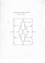
No. Think it through, the sources of the upper half are at a positive potential compared to ground and the lower at negative. With the resistor in the middle each half acts like a current source for the other.
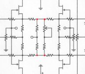
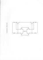
What resistor? According to schematic posted by JC, those four in the middle are not even connected.the resistor in the middle ?

If they would, schematic would show dots connecting the respective lines - see my attachment.
Oops...

--------------
Five minutes later, voice of boss in the background: "Now, get me that (beep) guy responsible for this (beep) schematic. I want to see him NOW!"
Attachments
Last edited:
JC, isnt this patented by Analog devices ?? Maybe expired ?? Scott should know ??
I believe the design idea is by Gosser.
Wow you follow everything, thats the first thing I thought but Roy's circuit was all bipolar (makes a great RF diff-amp). I would have to carefully read the claims but as you say it might be expired.


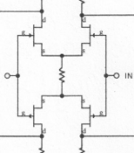
To me this looks like two CFA's with the resistor network providing bias and feedback. The common mode reference is at the input no need to ground that point, maybe it's a test measurement point? Are those LED's to set the output bias, seems to be some local feedback too?
Last edited:
the resistor in the middle ?
JC asked what sets the current. Isn't it the middle resistor ?
Attachments
JC asked what sets the current. Isn't it the middle resistor ?
Yes, of course. With 2SK170V/2SJ74V it typically would be in the range 50-100 Ohm.
Erno Borbely has a similar design without ground connection at the sources.
Except the sense of the gain is flipped, and you need the second half. Yet it does lead to it with a little work, I never thought the portion of the input that looks like a folded cascode buys you much.
Last edited:
Please remember everyone, the CORE of this circuit is 40 years old.
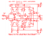
It was derived from a 100% bipolar topology that was designed for Alembic Inc as a line driver in 1970. The second schematic, that I released prematurely, because of so many 'questions' has more to it and can be confusing, but the EXTRA tabs are for SERVO connections, both differential and common mode.
It was derived from a 100% bipolar topology that was designed for Alembic Inc as a line driver in 1970. The second schematic, that I released prematurely, because of so many 'questions' has more to it and can be confusing, but the EXTRA tabs are for SERVO connections, both differential and common mode.
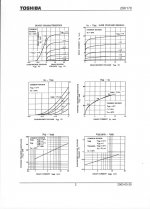
The middle resistor is NOT necessary for the nominal operation of this circuit, but it does control the idling current for the first (and second) stage. The resistor can be made variable to adjust for different Idss jfets. The derivation of the value of a fixed resistor can be done graphically from the jfet Id-Vgs graphs that are commonly available.
Last edited:
Erno Borbely has a similar design without ground connection at the sources.
Where he properly credited the topology to Mr. Curl.
Thanks,
Chris
A slight modification of this core circuit was originally used for the Grateful Dead line drive modules for the Wall of Sound in 1973, later used in the line out modules of the Levinson JC-2 preamp. Pictured on the next input here is a slightly advanced version of the older GD and Levinson modules, first used in the Vendetta Research 2'd stage and now in Parasound power amps.
- Status
- Not open for further replies.
- Home
- Member Areas
- The Lounge
- John Curl's Blowtorch preamplifier part II