For the CCS part, readers should know these articles.
It is obvious, that at least up to 200 kHz, a competently designed CCS will guarantee a constant current flow in the entire loop. The degrading CCS performance higher up can be compensated by an ....
The only varying currents are in the shunt element and in the load itself. It's obvious that those should be close to each other.
I think this is a massive difference to a series regulator supplying a current modulating load, with the modulated current flowing through the whole loop, rectifiers, transformer secondaries and (induced) primaries.
Of course, you could make your active circuit a more constant current like load.....go balanced....and/or folded cascodes.... but that's another (Blowtorch-) story.
Hi,
I didn't. Didn't have to.
I have been using shunt regulators since the last millenium for precisely these reasons...
But it seems some others would be well advised to familiarise themselves with the content of said column...
Ciao T
Indeed. That is why I was surprised that JC said 'Amazing!'. I though he would be well aware of it too....
jan
[snip]Of course, you could make your active circuit a more constant current like load.
Yes, and if you place a shunt reg near the load, or at least consider them as a single 'load', that's exactly what a shunt does!
jan
Actually, that begs the question: if the purpose of a shunt is to keep the total current constant, why do we design them as a voltage regulator?
If, otoh, we would design them as a current regulator, we would also negate the effects of any wiring between the shunt and the load!
No?
jan
If, otoh, we would design them as a current regulator, we would also negate the effects of any wiring between the shunt and the load!
No?
jan
Attachments
For the CCS part, readers should know these articles.
It is obvious, that at least up to 200 kHz, a competently designed CCS will guarantee a constant current flow in the entire loop. The degrading CCS performance higher up can be compensated by an ....
.
.
.
Of course, you could make your active circuit a more constant current like load.....go balanced....and/or folded cascodes.... but that's another (Blowtorch-) story.
A heavy localized supply line filter gives similar results: reduction in supply line frequency harmonics before the filter (because load current changes above the filter cut off frequency are localized around the load and active stage). Running active stages in class A also helps. The final point to remember is that signal load return currents should be terminated back at the driving source.
Actually, that begs the question: if the purpose of a shunt is to keep the total current constant, why do we design them as a voltage regulator?
If, otoh, we would design them as a current regulator, we would also negate the effects of any wiring between the shunt and the load!
No?
jan
Jan, I think if you are using an active local shunt, you will get better theoretical results if you feed it from a CCS. I think the main benefits in this set up is almost complete removal of AC on the supply line, so no radiation, so no noise coupling etc. For opamp based amplifiers, if you feed them from a CCS, for the local shunt you can use a zener or TL431 with a simple RC filter straight afterwards (to kill the zener or 431 noise at HF) to create a 'zero AC' supply feed. The high supply rejection of the opamp at low frequencies will take care of LF below the cut off frequency of the filter, while above the cut off, the opamp PSSR is aided by the filter. Expect over 110dB from a decent modern opamp at LF. Discrete based designs will usually not be as good as this, so more care with the shunt arrangement is needed.
Jan, I think if you are using an active local shunt, you will get better theoretical results if you feed it from a CCS. I think the main benefits in this set up is almost complete removal of AC on the supply line, so no radiation, so no noise coupling etc. For opamp based amplifiers, if you feed them from a CCS, for the local shunt you can use a zener or TL431 with a simple RC filter straight afterwards (to kill the zener or 431 noise at HF) to create a 'zero AC' supply feed. The high supply rejection of the opamp at low frequencies will take care of LF below the cut off frequency of the filter, while above the cut off, the opamp PSSR is aided by the filter. Expect over 110dB from a decent modern opamp at LF. Discrete based designs will usually not be as good as this, so more care with the shunt arrangement is needed.
Sure, you can use all kinds of refinements. I was asking the question if designing a shunt as a current regulator would not give better results than designing it as a voltage reg. For one thing, at the face of it, the current regulating shunt will also 'make invisible' the wiring between shunt and load which a voltage regulating shunt can't.
Maybe should sim both cases with similar parts, to see if there is a difference.
BTW You cannot 'kill' noise or 'take care of LF'. It is always a matter of more or less noise, or more or less LF. For a given set of parts or parts layout, some topologies may be better than others.
jan
Jan, I think if you are using an active local shunt, you will get better theoretical results if you feed it from a CCS.
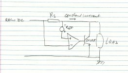
Maybe, maybe not. The concept circuit I scrabbled above does that, of course. It turns the combo shunt+load into a CCS
")
jan
Hi,
The shunt has the job to keep the voltage constant. If it is set as current reg it does not do that.
It is the job of the CCS to keep the current constant.
Incidentally, as no-one wanted bonus credits.
An optimally set up LM317 as series regulator offers around 80dB ripple rejection.
If the 317 is used as CCS and with a TL431 shunt the ripple rejection is around 126dB.
Ciao T
Actually, that begs the question: if the purpose of a shunt is to keep the total current constant, why do we design them as a voltage regulator?
If, otoh, we would design them as a current regulator, we would also negate the effects of any wiring between the shunt and the load!
No?
The shunt has the job to keep the voltage constant. If it is set as current reg it does not do that.
It is the job of the CCS to keep the current constant.
Incidentally, as no-one wanted bonus credits.
An optimally set up LM317 as series regulator offers around 80dB ripple rejection.
If the 317 is used as CCS and with a TL431 shunt the ripple rejection is around 126dB.
Ciao T
Hi,
The shunt has the job to keep the voltage constant. If it is set as current reg it does not do that.
[snip]Ciao T
You are right. It would only work if the 'raw DC' came from a voltage regulator itself, and that would defeat the whole thing.
jan
Amazing T!
Now, down to business.
SY, I know that you mean well, but you have not thought enough about the problems that you INTRODUCE when putting a LM317 close to your audio circuits. Look carefully at the Data Sheet on the LM317. Look at the LINE TRANSIENT RESPONSE, LOAD TRANSIENT RESPONSE, OUTPUT Z WITH FREQUENCY, OUTPUT NOISE, and finally the RIPPLE REJECTION WITH FREQUENCY. That is where the problems are. The 317 makes a fair ripple reducer, but it adds noise, transient distortion, and is almost not there above 1MHz, where all the digital action is.
Still it can be useful, IF a discrete series buffer is used, following it, making the LM317 ONLY a pre-regulator.
Shunt regulators are valuable, especially for class B circuitry, where the currents can change significantly. In the Blowtorch, the shunt regulator is only nominal, to create a constant load on the LM317, remove the transients, and any RF that leaks through.
Normal test equipment circuitry usually relies on power supply rejection to keep the problems of the LM317 out of the way, but it is not good enough for hi end audio.
Hi,
Sure, but almost anyone has LM317 in their parts stock, possibly 431's too. Plus the devices are well known.
The DN2540 is neat really a high performance CCS by any standards, a C4S (discrete circuit) can do way better, but that does not change the principles.
Equally, the shunt may be made "better" (lower noise, lower output impedance) than the TL431. But I believe such details are best left up to the individuals.
I was merely trying to illustrate the principle.
Ciao T
Hmmmm, i'd replace the LM317 CCS with a DN2540 CCS, see Pictures 12A/12B vs. 10A/10B in this article.
Sure, but almost anyone has LM317 in their parts stock, possibly 431's too. Plus the devices are well known.
The DN2540 is neat really a high performance CCS by any standards, a C4S (discrete circuit) can do way better, but that does not change the principles.
Equally, the shunt may be made "better" (lower noise, lower output impedance) than the TL431. But I believe such details are best left up to the individuals.
I was merely trying to illustrate the principle.
Ciao T
SY, I know that you mean well, but you have not thought enough about the problems that you INTRODUCE when putting a LM317 close to your audio circuits. Look carefully at the Data Sheet on the LM317. Look at the LINE TRANSIENT RESPONSE, LOAD TRANSIENT RESPONSE, OUTPUT Z WITH FREQUENCY, OUTPUT NOISE, and finally the RIPPLE REJECTION WITH FREQUENCY. That is where the problems are. The 317 makes a fair ripple reducer, but it adds noise, transient distortion, and is almost not there above 1MHz, where all the digital action is.
Depends on how you use it. Go beyond the datasheet and see the stuff that Dietz published. Likewise, if you use a chip shunt, you need extensive bypassing to get good results at megahertz.
Hmmmm, i'd replace the LM317 CCS with a DN2540 CCS, see Pictures 12A/12B vs. 10A/10B in this article.
You might check out Jung's follow-up in AX 4/09 using the topology I published a few months before that in the ImPasse article. Rejection of 150dB, with performance holding up well past 200kHz. A pair of DN2540 give stunningly good performance as a CCS.
But then, it is not a LM317 anymore.
What's "it?" Dietz's circuits? They're just a closer examination of how a straight 317 can be optimized. My comments about DN2540 have nothing to do with 317s other than pointing out that a DN2540 cascode is far superior in performance as a current souce (if you believe Jung) than a 317 or a 317/DN2540 cascode.
The way ThorstenL proposed was used in recording consoles and similar stuff that has multiple PCBs powered from single source, long time ago. First, there were plain non-flammable resistors and capacitors on each PCB to filter out ripples, minimize ripple currents through ground wires, minimize cross-talk and minimize dynamic resistance of power source on PCB. Current sources and Zeners (shunt regulators) further improved things. What's the point of arguing against such approach, if it helps to achieve desired results?
It is still a hybrid. However, the REAL PROBLEM is trying to make ONE regulator do ALL. It is almost impossible. Two regulators, or even three in series can do a better overall job, than one super, IC based regulator.
Perhaps an all out discrete design would be best, but it is not really affordable, or even justifiable.
Perhaps an all out discrete design would be best, but it is not really affordable, or even justifiable.
- Status
- Not open for further replies.
- Home
- Member Areas
- The Lounge
- John Curl's Blowtorch preamplifier part II