Ditto the AD MIMS accelerometers. The +/-100g unit is appropriate.
I haven't really thought out how one would do it with pressure, but they make a nice calibrator for a piston chamber, the .5% laser trim translates to about .05dB SPL which is better than anything less than NIST traceable B&K reference mics or something like that.
best = most?
Although you meant this rhetorically I think there's an undercurrent of more truth to it. Just as a side effect of being *able* to make a lot of air move, the radiating diaphragms often/typically move less to make any particular amount of air movement, so less FM. FM's fundamental to diaphragm movement, so yada yada.
Thanks,
Chris
I haven't really thought out how one would do it with pressure...
You don't have to, they're tiny and when glued to the dustcap, they give an excellent signal.
best = most?
Heheh. His was definitely a qualitative rather than quantitative assessment.
The room rattlers at BA did pretty well. Dick Burwen uses 30' concrete horns which are part of his foundation. There was a French fellow doing this even bigger, lost the pics.
Yeah, I've seen those. That's bordering on insanity though.
se
Simon, do you understand I disagree on any extremism that inevitably throws out baby with dirty water?
I have low wattage zero feedback designs to drive effective full-range speakers. I have designs to drive speakers with complex crossovers that sometimes have close to zero impedance dips. I have some designs to drive subwoofers by a negative output impedance. All of them satisfy requirements to drive own speakers. But if to select amps by criterion how close their output resistance is to zero we gain nothing but satisfaction of own meaningless criterion. Thanks God there is no such standard, so we still have some freedom to explore different possibilities.
Anatoliy,
I see in the stars that you have a new job, congratulations, hope it meets your needs.
I think there needs to be a bit of clarification. All real amplifiers have a complex output impedance that is also non-ohmic. In a typical solid state amplifier such as Bob Cordell's examples there is a maximum power output that increases with decreasing loads. In theory the power out should double as the load impedance halves. This is rarely the case due to what can be modeled as internal resistance in the power supply section. But even Thorsten knows that!
Then there is the output impedance of the output stage. This may or may not be reduced by feedback or specific design techniques. Most solid state amplifiers provide damping factor numbers to show just how low this output impedance can be at some given test frequency.
The standard for loudspeaker specifications used to assume the power applied to the loudspeaker under test was determined by the voltage measured at the device under test input terminals. This was then listed as a wattage based on the rated D.U.T. impedance. My one contribution was to start listing this as a voltage as that is what was actually measured and loudspeaker impedance is a complex number and issue.
So for now a loudspeaker is expected to be specified with a very low source impedance.
Now as many seem to have noticed you can make almost any given loudspeaker perform better for some tastes and musical genres with a non minimum impedance amplifier output.
Now in the case where you are designing an amplifier for a specific driver transducer this is quite a powerful approach and works well.
Now when you design an amplifier for a full range loudspeaker system advantages may be had for specific systems and combinations. This is of course boutique design. It is a valid design method, but it is not a general purpose design. A general purpose design most likely will never work as well as a boutique designed system, when done by a competent designer.
The downside of boutique design for the consumer is that although they may purchase the same amplifier and loudspeakers that perform very well as a set, they may not have a similar listening environment or musical tastes. Then again they may combine all individually well rated boutique components into a very bad system, due to not understanding why each part went best some other gear.
Now as we all have design preferences that will influence our views on how others design, listen and perform.
For example you often use tubes. They have several specific advantages over solid state parts. They also have some liabilities. The issue I find most interesting is they inherently have much greater out of band noise rejection. So it is quite reasonable that you find almost any power cord works well with your designs.
I for example have a power cord design the significantly reduces interference without adding any resistance. I can design this cord into a system as part of my power supply. Using other cords may degrade the performance of the entire system. But as it reduces costs and provides benefits I may choose to do so. That is a design decision.
Then there is the issue of power cord resistance. Most of the solid state capacitor filtered power supplies seem to have peak current draws 3 to 4 times the average current, some much more. In those cases a thinner wire gauge power cord can actually make a difference. (Not really a surprise.) But if you always use a choke filter power supply you may find there is no difference from something as simple as the small power cord resistance difference. This yields the classic story of the blind men examining the elephant.
Then the other issue raised was producing clean power from your own power plant. The issue in designing a rotating machine to produce electricity for low distortion is simple. The rotor has windings on several cores. You must have a gap between the cores to allow the wire in to be wound! This produces gaps in the magnetic field when the rotor moves. These gaps create disturbances in the power produced. So while you could design a lower distortion generator for the small power market, you wouldn't sell very many. Then people would tell you how unethical you are for charging such a high price for a product that is almost exactly the same as...
ES
Last edited:
boutique generator
Oehh, I/i know of a plastic surgeon who's both very proud of his collection of paintings, his audio set, and his backup generator setup.
Think i'll save this low distortion power plant story for the next upcoming wino art exhibition soirée.
Hi guys, solved all the world's problems when it comes to woofers? I am for a simple, large box with a really big loudspeaker or two. Of course, what do I know? '-)
Hello John
Is the large box sealed or vented.
Hi guys, solved all the world's problems when it comes to woofers? I am for a simple, large box with a really big loudspeaker or two. Of course, what do I know? '-)
I can add a ringing (Arf) endorsement for what's become known as a Linkwitz transform, but was originally just an almost overlooked little circuit element in S. Linkwitz's old 1980 _Speaker Builder_ article (not in the AES paper). It uses one inverting feedback gain stage to change any F_c and Q_c to (almost) any other F_c and Q_c.
Once, given the task of choosing an F_c and Q_c for a really really big woofer system (8 18"ers sealed boxes for home use) our small group settled on 8Hz and Q=0.5 - but your mileage will vary.
Might even be something that could be integrated into a high dollar preamp as a (very) custom option. Needs to be the same quality level, fersure.
Thanks,
Chris
Although this is second hand, a speaker designer friend of mine told me that some of the best bass he's ever heard was in a system that used a pair of these. The enclosures were a simple truncated pyramid. It wasn't really an enclosure per se as the bottom was left open and the drivers mounted at the top. The bottom was held up off the floor by about 4 to 6 inches with some simple feet.
> Sorta kinda like listening to an open baffle from the side ...
and rotated to appear a table ......
> Sorta kinda like listening to an open baffle from the side ...
and rotated to appear a table ......
Simon;
as I said before, when I design for some range of hi-fi speakers that are 2 or 3 way, and have dips almost down to zero, of course I would do all my best to ensure that the amp has low output resistance, and does not start wildly distorting when load resistance goes way down. And I am hundred percent sure that Stereophile would give very pleasant review to it. But it is not the single way to reproduce music, so some amp with very linear single-ended triode output would get very poor review, even if with corresponding speakers it will sound even better.
You know what happens when people enforce some artificial standards? Right, it forces the rest to pay money for "boutique" solutions that satisfy their tastes better.
Pavel,
If you apply a voltage to a dynamic driver/speaker a current flows.
This current flowing is what exerts a force on the diaphragm which hence is displaced from it's position.
In terms of variables outside the speaker that can change/generate the acoustic output the only variable is current, the acoustic output of the driver/speaker is dependent on the current in the voice coil and only the current in the voice and nothing but the current in the voice coil.
Now if we drive the speaker which reacts to current, only current and nothing but current with a voltage this voltage must be converted to a current somehow. This is done by the impedance of the speaker.
This impedance is composed out of the voice coil DCR, which is variable with temperature and hence will rise as we apply more power to the speaker, this is called power compression. Power compression in speakers which Sound On Sound showed as high as 5dB for some HiFi Speakers they tested) exists only with voltage drive and is cancelled using current drive.
Further the impedance of the speaker contains an inductive component. As this is created by winding a coil around a solid piece of steel (the pole piece and yoke) the current flowing through this coil with a given applied voltage will be distorted according to cubic function, that is creating odd order harmonics with the third highest and rising to the square of the applied power... This distortion mechanism is a direct function of the use of a constant voltage source to drive the speaker and it mainly shows up in middle and high frequencies where the voice coil inductance forms a large part of the drivers impedance.
In another twist, as the magnetic force is not constant for a given excursion of the driver and the Back EMF of the driver is not directly proportional to the diaphragms movement but also includes a signal variable term. As the Voltage Source driving the speaker short circuits the back-emf we have an electromechanical analog to the classic feedback loop, which, if the Amplifier used to drive the speaker includes looped feedback, extends into the actual amplifiers feedback loop. This mechanism causes unpredictable transient distortions and dominates with rising excursion.
So to me, knowing how a speaker actually works and what driving it with Voltage causes, driving a dynamic speaker with voltage is great nonsense, which does not prevent it from being the dominant mode employed. Even I do, as I need to maintain a system that is compatible with a wide range of commercial gear.
But just because everybody does it it is not necessarily right or optimal.
If I make an active speaker it will use current drive.
Ciao T
Anything else than voltage drive of the dynamic speaker is a great nonsense
If you apply a voltage to a dynamic driver/speaker a current flows.
This current flowing is what exerts a force on the diaphragm which hence is displaced from it's position.
In terms of variables outside the speaker that can change/generate the acoustic output the only variable is current, the acoustic output of the driver/speaker is dependent on the current in the voice coil and only the current in the voice and nothing but the current in the voice coil.
Now if we drive the speaker which reacts to current, only current and nothing but current with a voltage this voltage must be converted to a current somehow. This is done by the impedance of the speaker.
This impedance is composed out of the voice coil DCR, which is variable with temperature and hence will rise as we apply more power to the speaker, this is called power compression. Power compression in speakers which Sound On Sound showed as high as 5dB for some HiFi Speakers they tested) exists only with voltage drive and is cancelled using current drive.
Further the impedance of the speaker contains an inductive component. As this is created by winding a coil around a solid piece of steel (the pole piece and yoke) the current flowing through this coil with a given applied voltage will be distorted according to cubic function, that is creating odd order harmonics with the third highest and rising to the square of the applied power... This distortion mechanism is a direct function of the use of a constant voltage source to drive the speaker and it mainly shows up in middle and high frequencies where the voice coil inductance forms a large part of the drivers impedance.
In another twist, as the magnetic force is not constant for a given excursion of the driver and the Back EMF of the driver is not directly proportional to the diaphragms movement but also includes a signal variable term. As the Voltage Source driving the speaker short circuits the back-emf we have an electromechanical analog to the classic feedback loop, which, if the Amplifier used to drive the speaker includes looped feedback, extends into the actual amplifiers feedback loop. This mechanism causes unpredictable transient distortions and dominates with rising excursion.
So to me, knowing how a speaker actually works and what driving it with Voltage causes, driving a dynamic speaker with voltage is great nonsense, which does not prevent it from being the dominant mode employed. Even I do, as I need to maintain a system that is compatible with a wide range of commercial gear.
But just because everybody does it it is not necessarily right or optimal.
If I make an active speaker it will use current drive.
Ciao T
Hi,
I believe you are greatly confused. What you typed in this quote is a great fallacy. If it is not immediately obvious to you why " Results like VC's bumping backplates or cones crumbling" are not likely you may wish to peruse any of the good books on speakers that exist...
You are talking about damping. This a whole other kettle of fish. Lack of damping as such does not destroy any Speaker...
If you do not deal with the behaviour of the Mass/Spring resonant system of the driver and apply damping to it by other means (apperiodic damping was used with German Studio Speakers derived from the Eckmiller well into the 1980's, experimentally we used seamless voice coil formers made from Alu but they overdamped the drivers even for current drive).
When applying current drive Qe approaches infinity and the Drivers Qt becomes essentially Qm. Seas used to have some drivers with a very low (< 2) and linear Qm in their lineup, but last time I looked I could find them. But they seemed ideal for exploring current drive.
In a pinch you can even just equalisation to correct the frequency response (and yes, doing so MUST correct the impulse response too) as has been demonstrated in a number of publications...
At any extent, of course you cannot just take a generic off the shelf 3-way bass reflex box and drive it with a current source. Well, you can, but the results generally won't be pretty, though not woofer destructive (it should be obvious why).
Your question was based on not actually thinking about the real systems involved and how they behave, but simply what you could use as Bon Mot to shoot down an idea you failed to understand but disliked...
So what effect does it have on Qe (besides the obvious one)?
Yes, doesn't it just.
There is such an extensive number of misconceptions underpinning the above statement that I do not know where to start, so I won't. However, attenuating a driver does NOT create current drive (neither does putting a 1 Ohm resistor in series - which is what Bob Carver does in some of his Amp's for the "tube" output), it merely raises driving impedance to the driver somewhat. Current needs a source impedance that approaches infinity and not one that is a few ohm.
Ciao T
Agree for the most part, certainly for woofers it is most dangerous. At the high impedance peak(s) caused by the one (closed) or two (BR) fundamental resonance(s), voltage would sharply increase at the exact moment when excursion is already maximum and badly damped. Results like VC's bumping backplates or cones crumbling are likely.
I believe you are greatly confused. What you typed in this quote is a great fallacy. If it is not immediately obvious to you why " Results like VC's bumping backplates or cones crumbling" are not likely you may wish to peruse any of the good books on speakers that exist...
You are talking about damping. This a whole other kettle of fish. Lack of damping as such does not destroy any Speaker...
If you do not deal with the behaviour of the Mass/Spring resonant system of the driver and apply damping to it by other means (apperiodic damping was used with German Studio Speakers derived from the Eckmiller well into the 1980's, experimentally we used seamless voice coil formers made from Alu but they overdamped the drivers even for current drive).
When applying current drive Qe approaches infinity and the Drivers Qt becomes essentially Qm. Seas used to have some drivers with a very low (< 2) and linear Qm in their lineup, but last time I looked I could find them. But they seemed ideal for exploring current drive.
In a pinch you can even just equalisation to correct the frequency response (and yes, doing so MUST correct the impulse response too) as has been demonstrated in a number of publications...
At any extent, of course you cannot just take a generic off the shelf 3-way bass reflex box and drive it with a current source. Well, you can, but the results generally won't be pretty, though not woofer destructive (it should be obvious why).
Hence my earlier question to Thorsten how many woofers he had destroyed in the time when he says he used current drive for all his drivers.
Your question was based on not actually thinking about the real systems involved and how they behave, but simply what you could use as Bon Mot to shoot down an idea you failed to understand but disliked...
There are some other additional good reasons not to use current drive with woofers, such as the effect it has on Qes.
So what effect does it have on Qe (besides the obvious one)?
Hawksford in his paper identifies some interesting properties of current drive though, such as flattening out Bl irregularities.
Yes, doesn't it just.
Please note that in practice all mid and high drivers in passively filtered more way system have current drive to some extent, since they are usually attenuated in order to line up with the sensitivity of the woofer.
There is such an extensive number of misconceptions underpinning the above statement that I do not know where to start, so I won't. However, attenuating a driver does NOT create current drive (neither does putting a 1 Ohm resistor in series - which is what Bob Carver does in some of his Amp's for the "tube" output), it merely raises driving impedance to the driver somewhat. Current needs a source impedance that approaches infinity and not one that is a few ohm.
Ciao T
> Sorta kinda like listening to an open baffle from the side ... and rotated to appear a table ......
Hey Mike!
Yeah, something like that. Had some photos of it but can't seem to find them. I'll see if my friend still has them.
se
This is done by the impedance of the speaker.
This impedance is composed out of the voice coil DCR, ....
Further the impedance of the speaker contains an inductive component....
In another twist, as the magnetic force is not constant for a given excursion of the driver and the Back EMF of the driver ....
So to me, knowing how a speaker actually works ...
Thorsten, your view of speaker impedance is oversimplified.
Attachments
World's Largest Woofer
Well, I almost didn't admit to this; but part-way down on the page:
Worlds loudest subwoofers - crank up the bass
you will see the Concept Design woofer. I was part of the engineering team that came up with this 60" "woofer." The first time we drove it, it was sitting face down on the lab floor, and it started hopping around, and we scrambled to cut power to it. It was scary seeing a 200+ pound woofer bouncing around out of control. Once mounted in the panel truck and driven at 1/4 max excursion, it proceeded to blow the windshield and side windows out of the cab, destroyed the latch assemblies and blast the doors open, balloon the sheet metal of the truck all over, and we just plain couldn't keep the rear doors shut. It created so much pressure that using a B&K mic and a scope (outside the van) you could see the asymmetry in the resulting pressure field due to the non-linearity of the air: you can compress air to many ATMs, but only decompress it to -1 ATM before it creates a vacuum. Crazy stuff, I hated being around it when it was on; it gave an instant headache and you felt weak and queasy for a while afterwards.
Was it hifi or musical? Hell no. Was it designed to make max SPL playing by contest rules, yup.
Another crazy tale from the trenches of car audio...
Howie
Howard Hoyt
CE - WXYC-FM
UNC Chapel Hill, NC
www.wxyc.org
1st on the internet
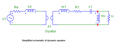
Joachim, that's correct, some of the elements of the schematics I posted are non-linear. Anyway, the speaker impedance may not be simplified to voice coil resistance, voice coil inductance and some mysterious "back EMF". This "back EMF" is just mechanical impedance and radiation impedance recalculated to electrical side of speaker schematics.
Pavel,
I merely presented three major points. You should not conclude that they represent all or even most of what I know or that I intend for them to represent a comprehensive picture. That would require several volumes without the references section and I have no time or will to write them.
The simplified model of a speaker you posted however is grossly oversimplified to reductio ad absurdum level and hence useless as it excludes all non-linearities...
Ciao T
Thorsten, your view of speaker impedance is oversimplified.
I merely presented three major points. You should not conclude that they represent all or even most of what I know or that I intend for them to represent a comprehensive picture. That would require several volumes without the references section and I have no time or will to write them.
The simplified model of a speaker you posted however is grossly oversimplified to reductio ad absurdum level and hence useless as it excludes all non-linearities...
Ciao T
Actually, there is a lot more to SUCCESSFUL speaker design that what can be commented on here. It is interesting that everybody has their opinions, but it is fairly amateur for the most part.
Of course, there is Beranek's law of speakers which goes: "If you design a loudspeaker and believe in the tradeoffs that YOU made, it is the BEST loudspeaker" Or something like that. '-)
Of course, there is Beranek's law of speakers which goes: "If you design a loudspeaker and believe in the tradeoffs that YOU made, it is the BEST loudspeaker" Or something like that. '-)
- Status
- Not open for further replies.
- Home
- Member Areas
- The Lounge
- John Curl's Blowtorch preamplifier part II