As usual, strong comments are made without any experience.
Let me give you one example of MY experience with line cords.
Personally, I don't like to spend extra money on line cords, but that does not say they are not audible. Please don't 'knock it' if you haven't tried it.
In any case, I had an interesting experience about 20 years ago, at CES.
A music producer that I had worked with since 1977, off and on, was doing an A-B test with power line cables.
Now, I had known and worked with this guy through 3 enterprises that he created. First, in the late 70's he had an audio magazine that I once contributed to.
At the same time, and after, he started and ran 'Crystal Clear Records' a direct disc recording company with many, many titles. I designed the electronics for his recording desk back in 1977. John Meyer (of Meyersound) was his technical consultant and he and I both recommended B&K 4133 condenser microphones running at full voltage.
A listening example of our efforts was: 'Arthur Fiedler and the Boston Pops' made in 1977 with direct disc mastering.
Anyway, he was at CES and was demoing power cords about 20 years ago.
Did we hear a difference? Yes we did, but he wanted so much money for these cables that we 'wrote it off'. Yet, the difference was there, AND for someone with means, actually a bargain for the improvement in the sound, which is difficult to get, once you have really good equipment, already. To say it is BS, is unfortunate. Live in ignorance, then. '-)
Please refer to Ohm's law concerning your old 15 amp AC. The wire in the transformer? GEEZ. It's the winding, not the gauge.
I think you completely missed my point. Yes, it's the number of turns in the primary that determines impedance. There's this thing called mutual inductance. The load applied to the secondary affects impedance too. And to say any more I have to dig out an old textbook, cause I don't remember all that stuff now.
So, if a person shorts the output of the secondary and the core starts to melt, the wire inside the transformer will still be a long wire and the gauge much less than a 6mm.
Hmmm ... so how the F#@$ does having a 6mm AC line help anything?

Here's a link to some history of early digital recordings.
It includes additional information on Crystal Clear Records and other items that John C. has mentioned.
http://goo.gl/rtn39
Just thought this might be interesting to some of you folks.
Cheers.
ZAP
It includes additional information on Crystal Clear Records and other items that John C. has mentioned.
http://goo.gl/rtn39
Just thought this might be interesting to some of you folks.
Cheers.
ZAP
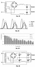
I would like to attract attention once again to chokes in power supplies of AB amps. Maybe some substractions from a textbook (its in russian) could help me to explain the point: chokes (10mH and more) help a bit to have more favorable spectrum of charging pulses, but they do increase voltage drops at filter capacitors during current consumption peaks and affect negatively sound dynamics.
As a conclusion, chokes are not recommended for AB amps, except for maybe configuration shown in fig.36, with external or well screened part of PS, and with abnormally big C3 and C4 (in order to compensate negative effects of chokes)
As a conclusion, chokes are not recommended for AB amps, except for maybe configuration shown in fig.36, with external or well screened part of PS, and with abnormally big C3 and C4 (in order to compensate negative effects of chokes)
Attachments
Vladimir; there are some other Russian books, for example: http://www.znvo.kz/images/book/dobrotvorskyin.zip
You are correct, Vlad. We call Fig. 36 a pi filter, in the USA. CLC
Could you disclose some general features of JC1 power supply, John?
chokes (10mH and more) help a bit to have more favorable spectrum of charging pulses, but they do increase voltage drops at filter capacitors during current consumption peaks and affect negatively sound dynamics.
As a conclusion, chokes are not recommended for AB amps, except for maybe configuration shown in fig.36, with external or well screened part of PS, and with abnormally big C3 and C4 (in order to compensate negative effects of chokes)
Vladimir, the problem is that you speak about very elementary issues. No professional and serious design engineer would ever design an LC or CLC PSU filter with component values that would cause unacceptable voltage drop (even during transients). You are rather teaching yourself than us. Please learn, Anatoliy has given you a survey of russian literature on power supplies.
Vladimir, the problem is that you speak about very elementary issues. No professional and serious design engineer would ever design an LC or CLC PSU filter with component values that would cause unacceptable voltage drop (even during transients). You are rather teaching yourself than us. Please learn, Anatoliy has given you a survey of russian literature on power supplies.
Pavel, I do not intend to teach anybody, this could have sence for persons like John and some others.
I share my subjective listening estimates of some conceptual solutions, concerning using chokes in power supplies of AB class amps. And my conclusion supported by many independent persons, including conclusions in textbooks. If one insist in using chokes, and achieves low voltage drops at transients, than L value is quite a small and one looses an initial target - suppression of HF PS voltage components.
Some people do accept bigger voltage drops during transients, they realize that sound dynamics can get worse, but they compensate it by positive effects of high L chokes, sound benefits in mid and high frequencies ranges.
Not everyone here is as experienced in power supply design as you PMA, and I hope not as 'full' upstairs, so that you cannot accept anything new.
It is well known that multiple section ripple filters work very well, because they multiply rather than add in their attenuation. In the early days, that is all we had.
Today, most of us just insert many thousands of microfarads and try to 'brute force' our way to low ripple. This causes real problems by generating peak currents, overheating transformers, transformer saturation, etc. But we do it anyway.
I rather like CLC filters, and I think they are a reasonable compromise with very high quality power supplies. The initial C can be lower in capacitance to reduce current peak surge, and the final C should be larger to create a clean ground return. Often the L should be damped with a resistor in parallel with it, in order to keep the circuit from ringing.
Vlad, the JC-1 is just a brute force power supply. NO inductors, just a huge toroid transformer, high speed 30 amp diodes, center tap, and about 100,000 uF of very good caps. The transformer has a higher voltage winding was well and this is separately filtered and actively regulated with a Zener controlled open loop dual Mosfet follower. This separates the supply modulation on current peaks, (like 60A) from the input and voltage driver stages. Only the followers get some modulation from the power supply during current peaks. The standing current is about 1.35A which gives about 300W idle power dissipation per channel, but only about 25W Class A. The rest is AB up to 800W into 4 ohms, much more into lower Z. However this amp is NOT designed for continuous operation below 4 ohms, but will do short term peaks effortlessly. It just overheats without a fan, if pushed too hard.
And why not fully balanced power amp designs from input to the power amp output, like CH or NP are offering?
In this case, you do have very small rail modulation with the signal frequency, but rather with total power changes, if you have still dynamic recordings ;-) , which are much lower in frequency.
Apart other advantages like lower rail voltages and therefore less power per active device in input-, amplification- and driver stage, etc.
Of course, delivering power into low impedances will be more demanding when going balanced.
And no, please do not bring up cost, we are talking SOTA power amps here, isn't it?
Hi,
Other than citing a number of Russian audiophiles (and clearly not the crowd formed around the Russian Sound Practices (Vestnika Ara) you have nothing supportive.
In fact both real circuits and simulations illustrate the reverse of your claim.
Now it is entirely possible that all of this started with someone who had little electronic understanding and was told "choke input supplies are better than capacitor input", then willy nilly stuck in some chokes and produced a mess that in essence did not work correctly. There are stories like that. They get repeated and become audiophile axiom's. I cannot comment on these in any reliable way, as they are all just chinese whispers.
I can only repeat, a correctly designed choke input supply offers better regulation (less voltage drop for a given change in current draw) than a capacitor input one, however the mains transformer windings need around 1.5 times the voltage used for capacitor input and the current drawn must not fall below the critical value.
Realistically, decent input chokes for 300B Amplifier are really big chunks of iron to work, the ones for a really high power class AB Amp would be humongous. But that says nothing about the underlying principles, only about implementation difficulties.
This is incorrect, one needs quit large (in the context) values (sizes too) of chokes for choke input supplies in order to achieve low voltage drops at transients, lowering the choke values increases supply line drop during periods of increased current draw.
This is EXPLICITLY NOT why Choke input supplies are used! Choke filters, using a suitably designed filter choke are what is used for this. Input chokes behave as exact analog to a PSU Capacitor, namely as means of energy storage. Energy may be stored in chokes or capacitors, both approaches are valid.
This is a highly subjective description. I have noticed that often when audiophile speak of "good dynamics" they actually mean "more compression" in terms of what is actually is happening.
To tie such subjective comments back to any technical features of choke input supplies (or any particular design feature) is rather difficult. It normally needs a combination of highly experienced and unbiased listeners who have an agreed descriptive vocabulary (so they describe compression as compression and not as "good dynamics") and extensive listening tests.
For fun, one of the subjects in our own tests (who also happens to be in the business) knew our amplifier (a Hybrid) did not double it's power from 8 to 4 Ohm. So kept complaining about "bad dynamics" until we had him bring one of his Amp's in (an all tube affair) which was on listening dynamically quite challenged next to our hybrid, despite having a power rating of around 2/3rds of our Amp.
So in the end we all agreed that in fact our amplifier had better dynamics, or more precisely a greater discrimination between loud and quiet and a much less stressed sound at high levels, however in this case without direct side by side comparison the repeated complaints where in fact that the system was too dynamic, too realistic and not the reverse, even though the language used suggested otherwise.
In the end the proof of the pudding is in the eating. Having chokes in my supplies makes my pudding tasty to me and to many others. Not everyone however would like a realistic sound and prefer HiFi artifice over reality, which is an entirely valid personal choice.
The problems come in when instead of Romy The Cat someone let Dog-ma's in...
The Dogma "Chokes in powersupplies for Class AB Amplifiers are bad" is false just as "All chokes in all powersupplies are good" is a false dogma.
One must see all possible techniques and choices in design as possibilities, understand them and apply in ways that bring most gain for the least outlay in commercial designs.
For diy designs we may dispense with any limitations. A 20W Mono Amplifer with a 100Kg a choke input power supply and 20Kg worth of heatsinks running at 100W Class A? Why not.
Ciao T
I share my subjective listening estimates of some conceptual solutions, concerning using chokes in power supplies of AB class amps. And my conclusion supported by many independent persons, including conclusions in textbooks.
Other than citing a number of Russian audiophiles (and clearly not the crowd formed around the Russian Sound Practices (Vestnika Ara) you have nothing supportive.
In fact both real circuits and simulations illustrate the reverse of your claim.
Now it is entirely possible that all of this started with someone who had little electronic understanding and was told "choke input supplies are better than capacitor input", then willy nilly stuck in some chokes and produced a mess that in essence did not work correctly. There are stories like that. They get repeated and become audiophile axiom's. I cannot comment on these in any reliable way, as they are all just chinese whispers.
I can only repeat, a correctly designed choke input supply offers better regulation (less voltage drop for a given change in current draw) than a capacitor input one, however the mains transformer windings need around 1.5 times the voltage used for capacitor input and the current drawn must not fall below the critical value.
Realistically, decent input chokes for 300B Amplifier are really big chunks of iron to work, the ones for a really high power class AB Amp would be humongous. But that says nothing about the underlying principles, only about implementation difficulties.
If one insist in using chokes, and achieves low voltage drops at transients, than L value is quite a small
This is incorrect, one needs quit large (in the context) values (sizes too) of chokes for choke input supplies in order to achieve low voltage drops at transients, lowering the choke values increases supply line drop during periods of increased current draw.
and one looses an initial target - suppression of HF PS voltage components.
This is EXPLICITLY NOT why Choke input supplies are used! Choke filters, using a suitably designed filter choke are what is used for this. Input chokes behave as exact analog to a PSU Capacitor, namely as means of energy storage. Energy may be stored in chokes or capacitors, both approaches are valid.
Some people do accept bigger voltage drops during transients, they realize that sound dynamics can get worse, but they compensate it by positive effects of high L chokes, sound benefits in mid and high frequencies ranges.
This is a highly subjective description. I have noticed that often when audiophile speak of "good dynamics" they actually mean "more compression" in terms of what is actually is happening.
To tie such subjective comments back to any technical features of choke input supplies (or any particular design feature) is rather difficult. It normally needs a combination of highly experienced and unbiased listeners who have an agreed descriptive vocabulary (so they describe compression as compression and not as "good dynamics") and extensive listening tests.
For fun, one of the subjects in our own tests (who also happens to be in the business) knew our amplifier (a Hybrid) did not double it's power from 8 to 4 Ohm. So kept complaining about "bad dynamics" until we had him bring one of his Amp's in (an all tube affair) which was on listening dynamically quite challenged next to our hybrid, despite having a power rating of around 2/3rds of our Amp.
So in the end we all agreed that in fact our amplifier had better dynamics, or more precisely a greater discrimination between loud and quiet and a much less stressed sound at high levels, however in this case without direct side by side comparison the repeated complaints where in fact that the system was too dynamic, too realistic and not the reverse, even though the language used suggested otherwise.
In the end the proof of the pudding is in the eating. Having chokes in my supplies makes my pudding tasty to me and to many others. Not everyone however would like a realistic sound and prefer HiFi artifice over reality, which is an entirely valid personal choice.
The problems come in when instead of Romy The Cat someone let Dog-ma's in...
The Dogma "Chokes in powersupplies for Class AB Amplifiers are bad" is false just as "All chokes in all powersupplies are good" is a false dogma.
One must see all possible techniques and choices in design as possibilities, understand them and apply in ways that bring most gain for the least outlay in commercial designs.
For diy designs we may dispense with any limitations. A 20W Mono Amplifer with a 100Kg a choke input power supply and 20Kg worth of heatsinks running at 100W Class A? Why not.
Ciao T
Hi,
Nice little tome. In my days we used to call them "Fliegenklatsche" (Flyswatter), because of their weight and size - the fly's never stood a chance...
Ciao T
Vladimir; there are some other Russian books, for example: http://www.znvo.kz/images/book/dobrotvorskyin.zip
Nice little tome. In my days we used to call them "Fliegenklatsche" (Flyswatter), because of their weight and size - the fly's never stood a chance...
Ciao T
One experienced designer wrote the following about the chokes in power supplies:
"When simulating power supply in the spice, I usually consider the behavior at the three kinds of varying loads:
1. Step, up and down. Gives the pulse response.
2. Sine over the constant level. Allows to estimate cross-modulation and dynamic nonlinearity.
3. Smooth ramping of current consumption from the minimum to maximum. Gives information on the linearity of the static characteristics.
The result of the first test should be aperiodic and preferably similar to the steps up and down.
The results of tests 2 and 3 are considered together. If the static and dynamic characteristics do not match, there are inertial-harmonic distortion. In this case, bass dynamics suffers and its legibility. This applies more to amplifiers with high modulation of current consumption. For these amplifiers, the most satisfactory result is obtained with the optimized CLC filter, it can be the best way to link together the static and dynamic load parameters.
LC or LCLC filter is better suited for amplifiers with low modulation of current consumption in the amplifier, where there is an active device loaded by current source at the output stage.
LC and LCLC filters have worse dynamic characteristics than static, which will be evident in the reduction of fidelity in the bass, and treated only with a significant increase in filter capacity (like Makarov), which brings the problem to infrasonic range."
Thorsten, I can can not manage to find any minor confirmation that LC filter could be good solution for AB amps (at the same time, it's the best solution for SE class A amps).
Last edited:
- Status
- Not open for further replies.
- Home
- Member Areas
- The Lounge
- John Curl's Blowtorch preamplifier part II