Hi,
Competently designed tube gear has distortion that is as low or lower than that of common speakers, for a given relative level, so if your contention is true it is equally applicable to speakers.
I would say given the long standing evidence on actual distortion audibility we may safely dismiss any charges of tubes being preferred for a given application due to them adding distortion in high fidelity applications.
Now Guitar and Bass Amplifiers are a different story. But remember, you can use Distorting Transistors as well, if not better to shape the sound of an Axe, depending on your style of music (Electro Harmonix Big Muff anyone?)
Ciao T
I would rather say that they (tubes) overlap the source material by their inherent distortion pattern, which is pleasing for many listeners, but not for everyone.
Competently designed tube gear has distortion that is as low or lower than that of common speakers, for a given relative level, so if your contention is true it is equally applicable to speakers.
I would say given the long standing evidence on actual distortion audibility we may safely dismiss any charges of tubes being preferred for a given application due to them adding distortion in high fidelity applications.
Now Guitar and Bass Amplifiers are a different story. But remember, you can use Distorting Transistors as well, if not better to shape the sound of an Axe, depending on your style of music (Electro Harmonix Big Muff anyone?)
Ciao T
Folks,
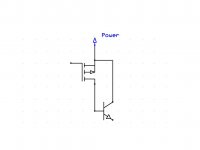
Seems at least on my browser the schematic does not display, here as attachment instead...
Ciao T
Looks like one of our old module schematics. I posted a stash of them from my archives that were not in Walt's history a few years ago.
EDIT - Yes that's one of John Cadigan's Model 40 Series, wonderful guy (passed away years ago) I learned a lot from him.
Last edited:
T
You mentioned doing a compound output stage with bipolars driven by complementary Fet (Mosfet?).
Previously I asked how many hidden common base/gate circuits are in an amplifier. I also showed the noise potential of power supply types.
Attached is the noise measurement results of the type of power supply I would expect in a power amplifier.
So if you use a complementary device off of the rails you have in effect a power supply noise follower.
I prefer to use a small split output coil transformer to provide a higher voltage drive rail and stay with followers that are driven by signals inside the cleaner (when designed correctly) core.
Please let me know what results you get.
ES
Attachments
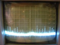
Ripple eater does a good job of cleaning this sort of thing up.
Not on a power amp and the effectiveness declines as frequency increases.
BW shown is 5 Mhz. Spectrum not V/T
T
You mentioned doing a compound output stage with bipolars driven by complementary Fet (Mosfet?).
Previously I asked how many hidden common base/gate circuits are in an amplifier. I also showed the noise potential of power supply types.
Attached is the noise measurement results of the type of power supply I would expect in a power amplifier.
So if you use a complementary device off of the rails you have in effect a power supply noise follower.
I prefer to use a small split output coil transformer to provide a higher voltage drive rail and stay with followers that are driven by signals inside the cleaner (when designed correctly) core.
Please let me know what results you get.
ES
Can you provide a circuit or reference? The description is a little to terse and I would like to better understand what you are describing.
The noise on your spectrum looks to be mostly power line related and less a function of the rectifier/cap combination. That is a really complicated problem to solve short of batteries.
I would rather say that they (tubes) overlap the source material by their inherent distortion pattern, which is pleasing for many listeners, but not for everyone.
This view is quite common.
However:
Possibly there is more to sound quality than THD alone (as long as THD isn't too high).
Possibly tubes are inherently more linear then FETs and FETs are inherently more linear than BJTs.
Possibly my present CDP sounds so good and analogue-like despite of its' < 0.3% THD+Noise, not because of it.
It might be, in some cases, for the reason of masking of non-harmonic digital artifacts by harmonic components related to music. This would also decrease the final resolution, which is also often preferred, believe or not.
Yes, in *theory*, that *might* work.
But I agree that lower resolution can sound 'better' sometimes, especially with inexperienced listeners.
jan
Demian
The noise has my noise generator added to the normal stuff that is there. We agree it is almost impossible to get rid of it. It is also at this point of very low source impedance. That is why I prefer not to couple it into the output.
Although the gain is one, using a standard follower allows other active parts to reduce the noise in the drive path.
ES
Thinking about it the voltage gain on the power rails noise is actually above one and will vary during operation!
Attachments
Last edited:
Hi,
Measurements of my gear are published in Stereophile, HiFi Critic, HiFi News and others. Please peruse these.
I do my measurements with 10K loads and I always design for 10K loads.
Ciao T
Do you have a set of FFT measurements to show here, for load about 10kohm (not 100kohm). Frankly speaking, I am more and more skeptical to verbal and written descriptions only, without support of trusted measurements.
Measurements of my gear are published in Stereophile, HiFi Critic, HiFi News and others. Please peruse these.
I do my measurements with 10K loads and I always design for 10K loads.
Ciao T
Hi,
Posted where, if I may ask?
Actually it's a model 50/HOS-50.
Ciao T
Looks like one of our old module schematics. I posted a stash of them from my archives that were not in Walt's history a few years ago.
Posted where, if I may ask?
EDIT - Yes that's one of John Cadigan's Model 40 Series, wonderful guy (passed away years ago) I learned a lot from him.
Actually it's a model 50/HOS-50.
Ciao T
I would rather say that they (tubes) overlap the source material by their inherent distortion pattern, which is pleasing for many listeners, but not for everyone.
Pavel, how such knowledgeable and smart engineer can blindly repeat this nonsense?

You may try, as hard as you can, to find such pleasing distortion pattern; I doubt you can find one.
Hi,
Not really. I mentioned a SFEF2 - that is a source follower driving an emitter follower.
You are right in EXPECTING such a supply, you would not catch me using one anything I'm serious about.
At the absolute minimum I use CRC Filter (yes, for poweramp's) with the second capacitor bypassed and snubbered. I normally set the R in RC filter to appx 30% of the effective DCR of the supply (that is if the supply drops 1V output voltage for 1A load I use 0.33 Ohm - 0.33 Ohm & 10,000uF form a 50Hz lowpass.
In AMR's amplifiers I design some R L directly into the PCB Layout, the big am has a 4 Cell RC filter at 100Hz per section and THEN a regulated supply...
For my current Pet Project I ordered some 1mH/50mOhm/10A chokes wound on Manganese/Iron torroid cores and a bunch of 18,000uF/71V Elna "For Audio" PSU Cap's.
Each supply will use a separate transformer winding, hybrid fast/soft & schottky rectifier bridge two cap's and two chokes with one choke in each line.
This supply has around a 10Hz turnover and -20dB at 100Hz with only 0.1 Ohm added DCR. Due to the ESR of the Cap's (including bypass) resonance of the Chokes the filtering is limited at 120dB around 500Kz but filtering remains significant (> 60dB) well into the lower two digit MHz.
Sorry, but working mostly with open loop circuits I have a fetish about PSU filtering and damping any resonances in the supplies. Even in circuits with ton's of feedback I find the audible problems introduced with generic circuitry rather troublesome.
That depends on how you do it.
If you use a standard Sziklai circuits with Lateral FETs you have a small Fet (say 2SK214) driving a bunch of big Fets of the opposite Sex (say 2SJ162).
The fun part of this is of course that output of the first stage is High Z and referenced to the (potentially noisy) rail which forms the reference for the input of the power transistor, which will now resist rather strongly coupling rail noise into the load...
My "really push the boat out" 300B SE Amps had less than 0.1mV noise, almost pure 50Hz, coupled into the circuit by the driver stages anode load and grid chokes and not the power supplies. Any noise from the supplies was much further down.
That used used a CLCLC supply with no electrolytucs incidentally (10uF/8H/50uF/6H/100uF) and further circuit design features that allowed around 26dB better PSRR at all frequencies than classic circuitry...
I expect to do much better with solid state as it is much easier work to get quiet...
Ciao T
You mentioned doing a compound output stage with bipolars driven by complementary Fet (Mosfet?).
Not really. I mentioned a SFEF2 - that is a source follower driving an emitter follower.
Attached is the noise measurement results of the type of power supply I would expect in a power amplifier.
You are right in EXPECTING such a supply, you would not catch me using one anything I'm serious about.
At the absolute minimum I use CRC Filter (yes, for poweramp's) with the second capacitor bypassed and snubbered. I normally set the R in RC filter to appx 30% of the effective DCR of the supply (that is if the supply drops 1V output voltage for 1A load I use 0.33 Ohm - 0.33 Ohm & 10,000uF form a 50Hz lowpass.
In AMR's amplifiers I design some R L directly into the PCB Layout, the big am has a 4 Cell RC filter at 100Hz per section and THEN a regulated supply...
For my current Pet Project I ordered some 1mH/50mOhm/10A chokes wound on Manganese/Iron torroid cores and a bunch of 18,000uF/71V Elna "For Audio" PSU Cap's.
Each supply will use a separate transformer winding, hybrid fast/soft & schottky rectifier bridge two cap's and two chokes with one choke in each line.
This supply has around a 10Hz turnover and -20dB at 100Hz with only 0.1 Ohm added DCR. Due to the ESR of the Cap's (including bypass) resonance of the Chokes the filtering is limited at 120dB around 500Kz but filtering remains significant (> 60dB) well into the lower two digit MHz.
Sorry, but working mostly with open loop circuits I have a fetish about PSU filtering and damping any resonances in the supplies. Even in circuits with ton's of feedback I find the audible problems introduced with generic circuitry rather troublesome.
So if you use a complementary device off of the rails you have in effect a power supply noise follower.
That depends on how you do it.
If you use a standard Sziklai circuits with Lateral FETs you have a small Fet (say 2SK214) driving a bunch of big Fets of the opposite Sex (say 2SJ162).
The fun part of this is of course that output of the first stage is High Z and referenced to the (potentially noisy) rail which forms the reference for the input of the power transistor, which will now resist rather strongly coupling rail noise into the load...
Please let me know what results you get.
My "really push the boat out" 300B SE Amps had less than 0.1mV noise, almost pure 50Hz, coupled into the circuit by the driver stages anode load and grid chokes and not the power supplies. Any noise from the supplies was much further down.
That used used a CLCLC supply with no electrolytucs incidentally (10uF/8H/50uF/6H/100uF) and further circuit design features that allowed around 26dB better PSRR at all frequencies than classic circuitry...
I expect to do much better with solid state as it is much easier work to get quiet...
Ciao T
T
OK I misread what you were doing. I avoid Sziklai bipolar outputs since all the ones I am familiar with fail long term.
It seems you have a good handle on how to handle power supply noise, although a bifilar common mode choke is often used to avoid dc saturation.
I like to use small caps across the rectifier diodes as they not only help damp any residual switching noise, but all four also end up as equal to just one straight across the filter cap. The inductance of the diode to cap wire helps to form an RF filter.
So how do you handle the Vas stage to avoid the same voltage rail issue?
Looking a bit more at it you will have some rail noise voltage gain in the output devices reduced a bit by Cis. As the rail impedance is almost zero and the load above that the issue still creeps in.
Last edited:
I like to use small caps across the rectifier diodes as they not only help damp any residual switching noise...
How do caps damp anything save for what little ESR they may have?
se
How do caps damp anything save for what little ESR they may have?
se
Because a diode at switch off can be modeled as a lossy resistor in addition to a discontinuous voltage source. The little L and ESR are not the main issues. so the C provides a path to the R
Hi Ed,
I would not do a bipolar Sziklai, the bias is just too twitchy and loves to run away. Lateral Fets in both positions are a slightly different proposition on thermals.
With Bipolar outputs incidentally I would classic followers with a normal Bias Spreader, which is AFAIK what JC does.
If you mainly like to deal with zero looped feedback SE Tube circuitry you need to learn how to kill noise, or it kills you.
CMC's are okay to deal with common mode noise, but their rejection of differential noise is near existing. Their advantage is they are dirt cheap. They have their uses.
The Manganese/Iron cores are made for rather esotheric high power SMPS applications. They have the needed saturation levels and incredibly high Al, so very few turns are needed (which aids pushing the resonance frequency WAY UP) while getting high inductance at high DC current.
The problem is finding a supplier who is willing to make you a modest QTY of unusual custom parts (they will all make a single sample, even free, but that does not go very far) without hitting you with a 1K Bucks small run fee...
Long story, a guy who lives now again in hong kong made his money (a fair bit I gather) with chinese restaurants in germany. He now often drinks at a place with good german beer at Knutsford Terrace I like to go to (think of it as heck city, where the grass is green and the girls are pretty without beer goggles) and we got talking and occasionally meet for a few brews.
One day when we where going to have a chat and a beer he comes in a wet behind the ears guy in tow. Turns out another German two years out of uni. He works for a German company that make precisely these "esotheric high power SMPS Chokes and transformers" somewhere on the Mainland (some place that sounded like it Sh..t in the name).
So I ask him "Can you make this?"? He says - I'll send you a sample.
So I say "I need 8pcs, but I have no idea if I ever actually buy any...".
So he says "How about you buy the next few rounds..?". A week later I had my chokes. Life has a funny way of helping you out.
So instead of Common mode chokes with no differentail filtering, I can have 0.5mH common mode and 2mH differential mode in a modest size package.
I prefer to not do that and just the softest switching diodes I can get (If voltages allow just schottky's) and add a schottky in series to the bridge output. I do tend to put a "fast" and "large" (by RF suppresion cap values) cap straight after this whole shooting match. Matter of taste.
Completely separate winding with schottky rectifiers, CLC with 3,3K/44mH (22mH * 2) /3.3k followed by a CCS and a Shuntegregulator running at a few 100mA (driver circuit is expected at 16mA per channel).
CCS will be in the 100K Impedance region to well past 10KHz and have an added choke (the inductors version of bypass Cap's - I use that trick a lot).
The Shunt Reg has around 50mOhm Z up to a few 100KHz (it is tres primitive with few active pars and no - it's not a Salas), above that the cap's take over.
Basically the usual...
To be honest, I have found that there is no such thing as "overdesigned powersupplies" in Audio.
This Amp we talk about will have a 1.5KVA Doughnut, even though it is expected to only do 180W/8R and 250W/4R per channel... I'd like bigger, but there is no space.
Stuff past a few MHz I don't worry, the Amp will have the bandwidth padded to 200KHz at the VAS output and run open loop except the LatFetSziklai (is that a Lfikai?) outputs...
Doing final calcs, the complementary bipolar LEFVAS (Load Effect Free VAS) stage will have nearly 50dB Degeneration (which really is funking funloving truckload), the input stage will have around 20dB degeneration and the J-Fet input stage will likely dominate the THD.
I expect < 0.01% or so while not going past quarter power pretty much at any frequency within the operating BW and without going to extreme circuitry (too much hard work), with some trimming can be better but I cannot be bothered anymore, my speakers are a little more than 0.1% THD between 300Hz and 3KHz, below and above you don't want to know...
Oh and and under 0.1 Ohm Zout..
I guess I am doing it mainly because I'm cheesed off by those who consistently insist you cannot make an Amp that measures well without NFB.
Given the values of Ciss etc, at those frequencies noise is reasonably easy to handle (I intend to put some ferrite beads on the leads of my "super chokes").
In the end you have to draw the line somewhere.
With >60dB noise rejection from the first cap in the PSU system at around 10MHz with the current intended PSU arrangement (I did run the actual parts to be used through a decent RLC analyser, so these are quite realistic numbers using realistic models) I refuse to loose sleep worring about it instead of loosing sleep by hopping on the good foot and do the bad thing if I have to loose sleep...
But you do raise a good point to most (CH, JC, GD et moi excluded - in fact GD outdoes me on powersupplies in a bad way and that takes some doing), powersupplies matter a lot. Often I can affect greater changes in sound by "tuning" the PSU a little then by dramatically changing the "active" side.
Ciao T
PS, GD is Gary Dews of Border Patrol, he once made a version of my Tube/LCR equalised Phonostage that used the kind of PSU I used for my build covering the whle Phono times four (one for each tube) and followed it by glowtube shunt regulators for each tube... We never compared our builds, but have a suspicion his sounds better....
My own supply was CLCLCLCLC with GZ34 rectifier, plus the mains transformer out of a Mullard 5-10 Poweramp for the HT...
That is 10uF/20H/120uF/20H/120uF/20H/120uF/20H/360uF with all caps film types and each choke two 10H pieces one in each supply line...
OK I misread what you were doing. I avoid Sziklai bipolar outputs since all the ones I am familiar with fail long term.
I would not do a bipolar Sziklai, the bias is just too twitchy and loves to run away. Lateral Fets in both positions are a slightly different proposition on thermals.
With Bipolar outputs incidentally I would classic followers with a normal Bias Spreader, which is AFAIK what JC does.
It seems you have a good handle on how to handle power supply noise, although a bifilar common mode choke is often used to avoid dc saturation.
If you mainly like to deal with zero looped feedback SE Tube circuitry you need to learn how to kill noise, or it kills you.
CMC's are okay to deal with common mode noise, but their rejection of differential noise is near existing. Their advantage is they are dirt cheap. They have their uses.
The Manganese/Iron cores are made for rather esotheric high power SMPS applications. They have the needed saturation levels and incredibly high Al, so very few turns are needed (which aids pushing the resonance frequency WAY UP) while getting high inductance at high DC current.
The problem is finding a supplier who is willing to make you a modest QTY of unusual custom parts (they will all make a single sample, even free, but that does not go very far) without hitting you with a 1K Bucks small run fee...
Long story, a guy who lives now again in hong kong made his money (a fair bit I gather) with chinese restaurants in germany. He now often drinks at a place with good german beer at Knutsford Terrace I like to go to (think of it as heck city, where the grass is green and the girls are pretty without beer goggles) and we got talking and occasionally meet for a few brews.
One day when we where going to have a chat and a beer he comes in a wet behind the ears guy in tow. Turns out another German two years out of uni. He works for a German company that make precisely these "esotheric high power SMPS Chokes and transformers" somewhere on the Mainland (some place that sounded like it Sh..t in the name).
So I ask him "Can you make this?"? He says - I'll send you a sample.
So I say "I need 8pcs, but I have no idea if I ever actually buy any...".
So he says "How about you buy the next few rounds..?". A week later I had my chokes. Life has a funny way of helping you out.
So instead of Common mode chokes with no differentail filtering, I can have 0.5mH common mode and 2mH differential mode in a modest size package.
I like to use small caps across the rectifier diodes as they not only help damp any residual switching noise, but all four also end up as equal to just one straight across the filter cap. The inductance of the diode to cap wire helps to form an RF filter.
I prefer to not do that and just the softest switching diodes I can get (If voltages allow just schottky's) and add a schottky in series to the bridge output. I do tend to put a "fast" and "large" (by RF suppresion cap values) cap straight after this whole shooting match. Matter of taste.
So how do you handle the Vas stage to avoid the same voltage rail issue?
Completely separate winding with schottky rectifiers, CLC with 3,3K/44mH (22mH * 2) /3.3k followed by a CCS and a Shuntegregulator running at a few 100mA (driver circuit is expected at 16mA per channel).
CCS will be in the 100K Impedance region to well past 10KHz and have an added choke (the inductors version of bypass Cap's - I use that trick a lot).
The Shunt Reg has around 50mOhm Z up to a few 100KHz (it is tres primitive with few active pars and no - it's not a Salas), above that the cap's take over.
Basically the usual...
To be honest, I have found that there is no such thing as "overdesigned powersupplies" in Audio.
This Amp we talk about will have a 1.5KVA Doughnut, even though it is expected to only do 180W/8R and 250W/4R per channel... I'd like bigger, but there is no space.
Stuff past a few MHz I don't worry, the Amp will have the bandwidth padded to 200KHz at the VAS output and run open loop except the LatFetSziklai (is that a Lfikai?) outputs...
Doing final calcs, the complementary bipolar LEFVAS (Load Effect Free VAS) stage will have nearly 50dB Degeneration (which really is funking funloving truckload), the input stage will have around 20dB degeneration and the J-Fet input stage will likely dominate the THD.
I expect < 0.01% or so while not going past quarter power pretty much at any frequency within the operating BW and without going to extreme circuitry (too much hard work), with some trimming can be better but I cannot be bothered anymore, my speakers are a little more than 0.1% THD between 300Hz and 3KHz, below and above you don't want to know...
Oh and and under 0.1 Ohm Zout..
I guess I am doing it mainly because I'm cheesed off by those who consistently insist you cannot make an Amp that measures well without NFB.
Looking a bit more at it you will have some rail noise voltage gain in the output devices reduced a bit by Cis. As the rail impedance is almost zero and the load above that the issue still creeps in.
Given the values of Ciss etc, at those frequencies noise is reasonably easy to handle (I intend to put some ferrite beads on the leads of my "super chokes").
In the end you have to draw the line somewhere.
With >60dB noise rejection from the first cap in the PSU system at around 10MHz with the current intended PSU arrangement (I did run the actual parts to be used through a decent RLC analyser, so these are quite realistic numbers using realistic models) I refuse to loose sleep worring about it instead of loosing sleep by hopping on the good foot and do the bad thing if I have to loose sleep...
But you do raise a good point to most (CH, JC, GD et moi excluded - in fact GD outdoes me on powersupplies in a bad way and that takes some doing), powersupplies matter a lot. Often I can affect greater changes in sound by "tuning" the PSU a little then by dramatically changing the "active" side.
Ciao T
PS, GD is Gary Dews of Border Patrol, he once made a version of my Tube/LCR equalised Phonostage that used the kind of PSU I used for my build covering the whle Phono times four (one for each tube) and followed it by glowtube shunt regulators for each tube... We never compared our builds, but have a suspicion his sounds better....
My own supply was CLCLCLCLC with GZ34 rectifier, plus the mains transformer out of a Mullard 5-10 Poweramp for the HT...
That is 10uF/20H/120uF/20H/120uF/20H/120uF/20H/360uF with all caps film types and each choke two 10H pieces one in each supply line...
Hi,
Posted where, if I may ask?
Actually it's a model 50/HOS-50.
Ciao T
Here in a thread somewhere.
The Model 50 was based on the earlier module series but that picture was certainly our art department. I like to credit folks that have been possibly forgotten, forgive me this nit. The cascoded VAS was a useful addition.
Both schematics follow each other in Walt's history.
ADI - Analog Dialogue | Op Amp Applications Handbook
- Status
- Not open for further replies.
- Home
- Member Areas
- The Lounge
- John Curl's Blowtorch preamplifier part II