Hi,
Yet the closed loop bandwidth is a function of the open loop one (and gain linearity)... You cannot divorce the two...
Ciao T
Also, see my PIM paper on my web site (CordellAudio.com - Home) where it is shown that it is modulation of the CLOSED LOOP BANDWIDTH that results in PIM, and, as such, the generation of PIM has little to do with open-loop bandwidth. The math does not lie.
Yet the closed loop bandwidth is a function of the open loop one (and gain linearity)... You cannot divorce the two...
Ciao T
We speak about VAS load by a resistor, and the VAS is inside feedback loop.
Ok, I thought that the discussion was about "VAS" loading to make a volume controll.
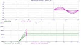
This is what I'm getting with a VGT (Variable Gain Transimpedance) volume controll, by stepping the volume controll resistors (I'm not even using all the "tricks" to get a low THD). It is ofcourse an open loop design.
BTW: It's an all BJT design, no obsolete parts.
Simulation is done by factory models.
Cheers
Stein
Sorry the file is to large, I'll reduce it.
Attachments
Last edited:
Hi,
Yet the closed loop bandwidth is a function of the open loop one (and gain linearity)... You cannot divorce the two...
Ciao T
The confusion still remains, take an amplfier with a 100MHz GBWP and make it have an Aol of 10^7 so open loop BW is 10Hz with some super process ultra-high Early voltage whatever and then make the >SAME< 100MHz GBWP amp have an Aol of 10k with an ordinary/bad process and an open loop BW of 10kHz and make a closed loop 20dB amp out of them they both are 10MHZ closed loop BW (within a very small error).
What John means by open loop BW is the 10Hz or whatever corner where the DC open loop gain breaks not the GBWP.
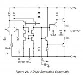
You could almost do the experiment with the AD829, it has an Aol of 100dB but I bet it's linear enough to feedback to the null pins from the output to push it up to 140dB or so. This part has lots of pins available, unfortunately the cap load helper R/C loads the VAS and is horrible for distortion even with no cap load (not my idea).
BTW is the 10H choke really needed in that RIAA preamp?
Attachments
Last edited:
Scott, I think it is cheating, since everything is optimized for low currents and high dynamic load resistance. Loading VAS only screws down input stage as well. Also, an output stage expects deep feedback around. High OL bandwidth opamp has to be designed, it is not enough to take low OL bandwidth opamp and load VAS on plain dumb resistance. It is a complete different story.
Darn, a guy can't get a few hours of sleep, without controversy breaking out. '-)
Now, I tried to be very diplomatic about what I think is a misunderstanding of what Charles Hansen is doing to change the open loop gain of his preamp.
I suspect that instead of decreasing the LOAD resistance, he is increasing the SOURCE resistance. This is obviously impossible with a typical op amp, but Charles and I use it all the time. I am using it in my newer phono stages that are discrete, for example. I also used it more than 35 years ago for microphone amps. (again discrete) I can't be absolutely sure of this, as I do not have access to his schematics, but I am fairly sure that I am right. IF I am right, then Scott has formed a false conclusion about Charles Hansen's most exotic preamp design.
There is also something 'half baked' about Scott's opinion of what I did with the HA911, then the best op amp for audio that either Dick Burwen or I could find (independently).
There, in the quest for modifying the open loop bandwidth, I added a 1 meg resistor from pin 8 to ground or the (-) supply, in order to open it from 100 Hz to perhaps 10KHz, 38 years ago. I EXPECTED the distortion to increase, especially since I had thrown away 40db (100x) global loop feedback, but with my trusty IM analyzer I got the OPPOSITE effect! I got LOWER distortion, instead! Why? Isn't this an interesting mystery? Of course, you have to be open to the concept, that it is even possible. I could repeat the test today, but I have other things to do, especially alone, without any technical support. Enough said.
Last edited:
pushing up the low frequency gain should have next to no stability consequence - you're moving the open loop gain pole, already > ~ 100x below the loop gain intercept for moderate gains - it is only contribuitng a fraction of a degree phase shift
while it would have to be really fast, especially at low gains, a unity buffer in the loop at the output would avoid loading, keep the added R,C largely bootstrapped
while it would have to be really fast, especially at low gains, a unity buffer in the loop at the output would avoid loading, keep the added R,C largely bootstrapped
IF I am right, then Scott has formed a false conclusion about Charles Hansen's most exotic preamp design.
There is also something 'half baked' about Scott's opinion of what I did with the HA911, then the best op amp for audio that either Dick Burwen or I could find (independently).
I added a 1 meg resistor from pin 8 to ground or the (-) supply, in order to open it from 100 Hz to perhaps 10KHz, 38 years ago. I EXPECTED the distortion to increase, especially since I had thrown away 40db (100x) global loop feedback, but with my trusty IM analyzer I got the OPPOSITE effect! I got LOWER distortion, instead! Why? Isn't this an interesting mystery? Of course, you have to be open to the concept, that it is even possible. I could repeat the test today, but I have other things to do, especially alone, without any technical support. Enough said.
I was never talking about his preamp, in a private conversation he made the same claims you make and BTW thank you for verifying, resistor loading VAS. Without all the data there is no way to determine what you saw and putting it to a supply might change the circuit bias.
Last edited:
There, in the quest for modifying the open loop bandwidth, I added a 1 meg resistor from pin 8 to ground or the (-) supply, in order to open it from 100 Hz to perhaps 10KHz, 38 years ago. I EXPECTED the distortion to increase, especially since I had thrown away 40db (100x) global loop feedback, but with my trusty IM analyzer I got the OPPOSITE effect! I got LOWER distortion, instead! Why? Isn't this an interesting mystery?
It depends on the circuit design. In some circuits, you may get lower distortion with the VAS loaded, especially by a particular, selected resistor value. It usually is the case when input pair is not tailed by CCS and has some degenerating emitter resistors. In my bipolar input Dispre 2 there is a heavy emitter degeneration of input LPTs and these resistors are supplied by resistor, not CCS. It works like tail current modulation (discussed currently), but has pretty bad CMR. Together with certain, defined resistor VAS loading the non-linearities subtract and you get minimum of distortion. But this concept is not universally transferable.
PMA, my take on it is that it 'quaisi' voltage drove the complementary transistor darlington output stage, as the nominal drive Z was 100 meg ohm, was reduced to 1 meg ohm. I stand by my conclusions, until shown different. It is easy, not that difficult, especially when I came into electronic engineering in the '60's, when we believed in non-linear beta as the fundamental distortion contributor.
It depends on the circuit design. In some circuits, you may get lower distortion with the VAS loaded, especially by a particular, selected resistor value. It usually is the case when input pair is not tailed by CCS and has some degenerating emitter resistors. In my bipolar input Dispre 2 there is a heavy emitter degeneration of input LPTs and these resistors are supplied by resistor, not CCS. It works like tail current modulation (discussed currently), but has pretty bad CMR. Together with certain, defined resistor VAS loading the non-linearities subtract and you get minimum of distortion. But this concept is not universally transferable.
Excellent PMA many are fooled by fortuitous cancellation (I wish I could forget).
")
What a breakthrough! A more than 100 cancellation of the distortion, primarily at 60 Hz, in an IC with a 1 meg added internal load across the driver stage, AND a slight improvement in slew rate.
John;
it does not mean that any ic would benefit from such modification. I believe Scott's designs are very well optimized, so all attempts to improve them may screw down results of his efforts.
Scott,
Why don't we instead compare apples with apples, shall we?
Let us say we have a discrete OPA with 120dB DC Gain and 20Hz bandwidth with an SE class A output.
Due to the vagaries of epectronic design the 20Hz bandwidth corner is modulated by around +/-2Hz over the whole swing of the OPA VAS. What is the effect in band for a 20Hz-20KHz bandwidth? Non-Linearity (whatever you want to call it) from bandwidth modulation.
Now let us take the OPA and degenerate input by 20dB and VAS by 40dB (Yes, this will loose us output swing and increase noise, we may need more supply current, all no-no's in IC design, but "fair game" for audio). We will find we need to change our compensation to a much smaller one as well.
We now have appx. 70dB DC gain (because the VAS operates in current input mode, and degenerating raises it's input impedance and thus the gain if the IPS) 70dB gain at 1KHz and even close to 70dB at 20KHz. There is no or very little bandwidth modulation, as the parameters that cause it are all stabilised much better due to degenerating the devices Gm.
What is the in band effect? The previous distortion mechanism has disappeared and the whole amplifier behaves with an equivalent linearity to the above for other non-linearity factors.
So, here we have a simple case where widening open loop bandwidth does help to remove sources of distortion without penalties elsewhere.
No, but I had it, so why not use it? This article was written in a golden age in Britain where almost every little town had a Shop called "Maplin" who stocked Audio grade Op-Amp's, Philips Tinfoil & Polystyrene precision capacitors, SLA Batteries and chargers and even Velleman K4000 Tube Amplifier Kits (100W; 4 * EL34 per channel) and high grade Audax Speaker drivers including that legendary 34mm Dome Tweeter found in many a BBC Monitor.
They even stocked cheap and good 10H Chokes... Next door was one called Tandy (Radioshack UK) who stocked other interesting speaker drivers and parts.
Tandy closed shop ages ago, one of the local ones I knew is now a Betting Shop. The other Shop's are still there and are still called Maplin. The sortiment of electronic parts is rather dire nowadays, in part by company policy and in part by deletion of nice parts by their makers (and made worse by the company policy to stock 1pc of everything in the catalog, but only 1pc).
The main selling items are PC Parts, Gizmos and Bedroom DJ Gear. Indeed a sad sight...
Ciao T
The confusion still remains, take an amplfier with a 100MHz GBWP and make it have an Aol of 10^7 so open loop BW is 10Hz with some super process ultra-high Early voltage whatever and then make the >SAME< 100MHz GBWP amp have an Aol of 10k with an ordinary/bad process and an open loop BW of 10kHz and make a closed loop 20dB amp out of them they both are 10MHZ closed loop BW (within a very small error).
Why don't we instead compare apples with apples, shall we?
Let us say we have a discrete OPA with 120dB DC Gain and 20Hz bandwidth with an SE class A output.
Due to the vagaries of epectronic design the 20Hz bandwidth corner is modulated by around +/-2Hz over the whole swing of the OPA VAS. What is the effect in band for a 20Hz-20KHz bandwidth? Non-Linearity (whatever you want to call it) from bandwidth modulation.
Now let us take the OPA and degenerate input by 20dB and VAS by 40dB (Yes, this will loose us output swing and increase noise, we may need more supply current, all no-no's in IC design, but "fair game" for audio). We will find we need to change our compensation to a much smaller one as well.
We now have appx. 70dB DC gain (because the VAS operates in current input mode, and degenerating raises it's input impedance and thus the gain if the IPS) 70dB gain at 1KHz and even close to 70dB at 20KHz. There is no or very little bandwidth modulation, as the parameters that cause it are all stabilised much better due to degenerating the devices Gm.
What is the in band effect? The previous distortion mechanism has disappeared and the whole amplifier behaves with an equivalent linearity to the above for other non-linearity factors.
So, here we have a simple case where widening open loop bandwidth does help to remove sources of distortion without penalties elsewhere.
BTW is the 10H choke really needed in that RIAA preamp?
No, but I had it, so why not use it? This article was written in a golden age in Britain where almost every little town had a Shop called "Maplin" who stocked Audio grade Op-Amp's, Philips Tinfoil & Polystyrene precision capacitors, SLA Batteries and chargers and even Velleman K4000 Tube Amplifier Kits (100W; 4 * EL34 per channel) and high grade Audax Speaker drivers including that legendary 34mm Dome Tweeter found in many a BBC Monitor.
They even stocked cheap and good 10H Chokes... Next door was one called Tandy (Radioshack UK) who stocked other interesting speaker drivers and parts.
Tandy closed shop ages ago, one of the local ones I knew is now a Betting Shop. The other Shop's are still there and are still called Maplin. The sortiment of electronic parts is rather dire nowadays, in part by company policy and in part by deletion of nice parts by their makers (and made worse by the company policy to stock 1pc of everything in the catalog, but only 1pc).
The main selling items are PC Parts, Gizmos and Bedroom DJ Gear. Indeed a sad sight...
Ciao T
Hi John,
This is interesting.
The HA911 (what a fateful type number, did Harris [and Porsche] knew something back then - are they in on the conspiracy?) runs at very low currents.
So connecting a resistor to the negative rail from the VAS collector will increase the VAS current. It will also introduce a fixed offset term that will force the input stage and VAS into a different balance closed loop.
Without extensive analysis it is hard to be sure what changed and how (and I really don't have the time), but lowered distortion and increased slew rate are not that hard to predict in context, especially given the VAS transistor is a PNP one, at that time that was a complete POS.
Of course, no doubt some will focus on how a resistor was attached to the VAS output node and nothing more, but doing so in this cases I believe misses the point.
Ciao T
There is also something 'half baked' about Scott's opinion of what I did with the HA911, then the best op amp for audio that either Dick Burwen or I could find (independently).
There, in the quest for modifying the open loop bandwidth, I added a 1 meg resistor from pin 8 to ground or the (-) supply, in order to open it from 100 Hz to perhaps 10KHz, 38 years ago.
This is interesting.
The HA911 (what a fateful type number, did Harris [and Porsche] knew something back then - are they in on the conspiracy?) runs at very low currents.
So connecting a resistor to the negative rail from the VAS collector will increase the VAS current. It will also introduce a fixed offset term that will force the input stage and VAS into a different balance closed loop.
Without extensive analysis it is hard to be sure what changed and how (and I really don't have the time), but lowered distortion and increased slew rate are not that hard to predict in context, especially given the VAS transistor is a PNP one, at that time that was a complete POS.
Of course, no doubt some will focus on how a resistor was attached to the VAS output node and nothing more, but doing so in this cases I believe misses the point.
Ciao T
Power Amp with Hawksford VAS and EF triple here Audio Amplifier Design and Circuits | hifisonix.com. This is a practical running amplifer that I've been using since 2007. It was recently (October) modified from Cdom compensation to TMC and the VAS loading you see in the circuit was removed to raise the loop gain. I will post up the modified circuit some time - after I have completed my current project.
It does sound different, but I'll leave it at that for now until I have spent more time with it to form an opinion.
BTW, re Cdom discussion earlier I was referring to local feedback around the VAS stage, not global feedback.
It does sound different, but I'll leave it at that for now until I have spent more time with it to form an opinion.
BTW, re Cdom discussion earlier I was referring to local feedback around the VAS stage, not global feedback.
Last edited:
It would seem that fellow designers would rather 'critique' rather than come to understand something that would not be normally predicted. However, that appears to be what is happening here. Wavebourn, you could duplicate my test if you were so inclined. But apparently you would rather believe that it is irrelevant. So be it.
For the record, I have not used a Harris HA911 for anything useful for the last 35 years, but it WAS the best device at the time. Dick Burwen used selected units and put them in modules that he sold to Mark Levinson for the LMP-2 preamp, a professional mixer, and the LNC-2 crossover. Later, I designed lower current electronics to replace these devices. We used the audio mixer designed by Mark Levinson for the stage monitors for the Watkins Glen event in 1973 (approximately 500,000 people attended) and the roadies told me later that it worked just fine. Later analysis of a selection of devices showed a large range of open loop non-linearity with these devices, so hand picking them was a good thing. Still, I went back to discrete, comp differential jfet design for Mark Levinson and the Grateful Dead, and I have stayed with this sort of design until today, for my most exotic efforts.
All I can ask anyone to do is to use IC's, beat me at my own game of audio design, and get rich and famous for it. Then, I will know that IC's have 'come of age' and I can concentrate on systems design in future. No excuses however, will impress me, if you fail.
- Status
- Not open for further replies.
- Home
- Member Areas
- The Lounge
- John Curl's Blowtorch preamplifier part II