Those would be?
Change in resistance, heating of the insulation, change in conductor distance at the bends due to increased flexing, change in capacitance....
I would like to return to the JC 3, as it seems to be a SOTA opamp phono preamplifier.
I am curious about the design of the output stage, as it seems to lose linearity into 600 ohm load
Parasound Halo JC 3 phono preamplifier Measurements | Stereophile.com
I do not get this worsening even into 50 ohm load with my preamp output stage, that's the reason why I am asking.
The attached plot is into 32 ohms.
Attachments
Last edited:
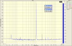
Pavel, just a side question if you don't mind. I see missing H5 & H7. I've seen that in other circuits, too, but don't know why. As low as they are in your example I can't think you'd ever hear them, but just out of technical curiosity, is this a pattern that has a known cause? It's not the first time I've seen it is why I ask.
Change in resistance, heating of the insulation, change in conductor distance at the bends due to increased flexing, change in capacitance....
I hope you wear ear plugs when observing these effects with real speaker loads. I've only observed the mechanical effects when arc welding at 100's of amps, or maybe shorting a 1000amp-hr battery.
Pavel, just a side question if you don't mind. I see missing H5 & H7. I've seen that in other circuits, too, but don't know why. As low as they are in your example I can't think you'd ever hear them, but just out of technical curiosity, is this a pattern that has a known cause? It's not the first time I've seen it is why I ask.
Thanks for your question. Frankly speaking, I am not so sure about special importance of the 7th and 9th, if they are somewhere at -130dB and less.
The absence of 5th and 7th in my plot most probably results from
1) inherent linearity of the output stage (diamond buffer with idle current at 40mA)
2) overall excellent linearity achieved also with a help of global feedback.
Usually the 5th is still visible in the output stage. It does not necessarily indicate cross-over distortion. The cross-over distortion is indicated by almost constant level of high order harmonics up to very very high orders. The 5th and 7th is definitely present in my design, but it may lie below measurement noise floor or even preamplifier noise floor.
Last edited:
I would like to return to the JC 3, as it seems to be a SOTA opamp phono preamplifier.
I am curious about the design of the output stage, as it seems to lose linearity into 600 ohm load
Parasound Halo JC 3 phono preamplifier Measurements | Stereophile.com
I do not get this worsening even into 50 ohm load with my preamp output stage, that's the reason why I am asking.
The attached plot is into 32 ohms.
Since when is 10 volts into 600 ohms relevant to a phono stage? Headphone amp? Sure. Phono stage?
Are you driving that 32 ohms with 10 volts? If so, you're talking about 3 watts. Are we talking phono stages or headphone amps?
se
I hope you wear ear plugs when observing these effects with real speaker loads. I've only observed the mechanical effects when arc welding at 100's of amps, or maybe shorting a 1000amp-hr battery.
Did you read the quote? At the level of measurement, I suspect those are real issues. The clue is the speaker wire resistance. 65 milliohms of 10 gauge would be 32 feet! So the test samples clearly were smaller gauge and looking at it some must have been 24 gauge! Yeah 4.5 amps would melt that
")
Since when is 10 volts into 600 ohms relevant to a phono stage? Headphone amp? Sure. Phono stage?
Are you driving that 32 ohms with 10 volts? If so, you're talking about 3 watts. Are we talking phono stages or headphone amps?
se
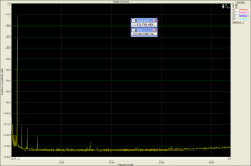
Well, not in the plot shown. Anyway, the load is 32 ohm - about 20 times lower impedance than 600 ohm.
Are we speaking phono stages or headphone amps - in my designs almost no difference. I can drive 32 ohm with my line stages, and also the phono stage has the capability to drive loads like 100 ohm.
I can make a measurement of the phono stage at 10V/600 ohm, in case you are interested in it.
This is really -----. Who cares whether the JC-3 can drive 600 ohms or so? It was NEVER designed for that, and it is the OPA2134 on the output that is the limitation. Big Deal! Why the reviewers tested at that impedance was just to MEASURE some significant distortion, I guess. Feedback tends to hide it, you know.
Well, not in the plot shown. Anyway, the load is 32 ohm - about 20 times lower impedance than 600 ohm.
And about 300 times lower than the lowest impedance a phono stage would ever likely see.
So what's your point?
se
Okay, by the time I have measured my phono at 10Vp/600 ohm. Any comments, Steve?
What's my point? My point is that the distortion into 600 ohms indicates to 'something'.
"Something" perhaps. But not "something" relevant that I can see.
se
I couldn't tell from the Stereophile article pic - but I see only one wire bundle from the ps xfmr to the ps reg board - is it really "dual mono" as advertised - completely isolated dual sec for each channel - or just separately regulated from common secondary?
some would even insist that dual xfmr are required to qualify as "dual mono"
some would even insist that dual xfmr are required to qualify as "dual mono"
Did you read the quote? At the level of measurement, I suspect those are real issues. The clue is the speaker wire resistance. 65 milliohms of 10 gauge would be 32 feet! So the test samples clearly were smaller gauge and looking at it some must have been 24 gauge! Yeah 4.5 amps would melt that
4.5A rms into an 8 Ohm speaker sounds loud to me.
Did you read the quote? At the level of measurement, I suspect those are real issues. The clue is the speaker wire resistance. 65 milliohms of 10 gauge would be 32 feet! So the test samples clearly were smaller gauge and looking at it some must have been 24 gauge! Yeah 4.5 amps would melt that
fusing current for 24 AWG copper wire ~ 30 A
insulation melts lots lower but even some conservative safety standards allow 3.5 A in 24 AWG "open wire"
certainly teflon insulated 24 gage would be happy at 4.5 A
4.5A rms into an 8 Ohm speaker sounds loud to me.
(Hand to ear) Eh, speak up, why do you always mumble? (True unhappy client story!)
The cited blog came to the conclusion the article finding cable differences was flawed. I think the basis of comparison was flawed also.
Now 162 watts average into a loudspeaker seems loud, but I was just at a small ballpark. The loudspeakers I installed 18 years ago were rated for 103.1 db/w @ 1M. Someone else (Low bidder) had added speakers to cover new seating that were 90 db/w @ 1M.
So the new loudspeakers at 4.5 amps would have produced 105.8 db @ 1M (Power compression comes into play and that actually is a fairly good number for their maximum power.) As this is a minor league ballpark the level would need to be 95 db at the farthest seats. So the throw of those added speakers would be 132 inches! The ones I used handled a bit more power and could throw 54 feet, which was just adequate.
The operator mentioned they could not get a good level balance for the entire ballpark. It just wasn't loud enough for the new section no matter what they did.
So there really are cases where 4.5 amps ain't loud enough even for indoor use as some audiophile loudspeakers can be as low as 82 db/w @ 1M.
fusing current for 24 AWG copper wire ~ 30 A
insulation melts lots lower but even some conservative safety standards allow 3.5 A in 24 AWG "open wire"
certainly teflon insulated 24 gage would be happy at 4.5 A
Yes 30 amps would blow open 24 gauge wire, but my mental image was of 24 gauge PVC clear insulated zip style "speaker" wire that I suspect really would have melted insulation at 4.5 amps. Don't know for sure and not really worth trying!
PMA, I have been very frank and open to you, today and previously. Please, don't appear to be 'marketing' your own design at my expense. The original JC-3 was designed to be placed inside the JC-2 as add on boards. This is why the boards are so small and with limited current. They were designed for a 50K load, initially. Later, it was decided to put the boards in a separate package, and we had a whole set of other problems, including extra cost, power supply separation (for low hum and Xtalk) and material availability. For example, the first case was steel, which I insisted be changed to aluminum, as I could hear its effects. The JC-3 is a good design, not my best, BUT Parasound has a tremendous problem getting enough jfets for the JC-1,JC-2, and other power amps of my design, and they insisted that I NOT use jfets on the input of this design. They already search the world for jfets, as is.
I did not write the description of the JC-2 for anyone, and sometimes reviewers take liberties with their interpretation of what they see, or are told. This was pointed out first, by Charles Hansen, (another competitor) more than 1 month ago.
I did not write the description of the JC-2 for anyone, and sometimes reviewers take liberties with their interpretation of what they see, or are told. This was pointed out first, by Charles Hansen, (another competitor) more than 1 month ago.
- Status
- Not open for further replies.
- Home
- Member Areas
- The Lounge
- John Curl's Blowtorch preamplifier part II