....
I only gave you my own opinion.

Thanks for taking the time to do that.
Hi,
......
Ciao T
Thanks for the interesting info. About the amplifier you provided a link to, is there more info available, preferably in English ?
B.t.w. since you recommend it, did you build and listened to it yourself ?
The Sim's, the sims...
Folks,
So let me summarise where this whole set of simulations regarding the JC-3's inner loop has left us:
1) We have several simulations that use more modern and arguably by far more linear parts and are more or less similar to the original design. Non have shown either 19 + 20KHz IMD spectrae, 76 + 80KHz Spectra or TIM diagnostic signal waveforms. All Show 1KHz or 10KHz HD only.
2) One Sim shows no appreciable difference between the inner loop connected and not at 1KHz, suggesting to me that the Output Stage transistor models are not very good, as even in Class A an EF2 stage is not THAT low distortion that 40dB+ change in feedback factor for the output stage have no effect whatsoever at lower order HD.
3) Another Sim shows that connecting the inner loop reduces higher order HD at the expense of more lower order HD (2nd to be specific) which would be case if the higher order terms are a mixture of multiplication products between multiple distorting stages and "re-entrant" distortion.
4) A third Sim using supposedly the same software, settings and models shows the opposite of the second sim (3) and was posted after the second one appeared to show that in fact the inner loop works as advertised. It shows that in fact things are as those promoting the superiority of the global loop claim.
5) We have seen the results of other sim's that basically had nothing to whatsoever with the actual JC-3 Circuit, one wonders seriously why anyone would do such a thing, as it will not provide relevant answers. Of course, the more realistic sims also show veritable cornucopia of confusion, as clearly only one of the three shows the real situation.
So, right now we have a set of results that tell us basically funk all.
It illustrates rather magnificently the limitations of simulators, but sadly we are no better off than before and the question if we are best off maximising loop gain in the main (outer) loop or best off maximising linearity of all stages before closing the main (outer) loop by using degeneration as well as local loops remains unanswered.
6) Inductive analysis based on Bruno's conclusion suggests that the latter may be a better choice and we have one set of simulations that appear to support this. For me this is good enough to keep degenerating and using inner loops. However there evidence here to support "maximise loop gain". So we all just pick tye evidence we like and disregard that which we don't.
So we are all right and all happy. Or we are all wrong and all unhappy.
Meanwhile I think I might actually for fun build that Evolve Lateral Fet Open Loop Amp I linked earlier instead of messing around with "improved goldmund's" and apply my suggested switchable feedback option with 20 and 40dB loop feedback available.
This may shed by far more light than all the debate so far, which has promptly run into paralysis through overanalysis and deliberate distortions.
Ciao T
Hi.
translate.google.com
I use Google Chrome and it is set to automatically translate Japanese, Chinese and French (German and Russian I normally manage).
Sorry, not build or listened, but it looks very interesting and seems to combine good objective performance with design techniques that tick all the other boxes discussed in this thread (local degeneration only, except output which is compound feedback pair), no global feedback and so on.
What I also find attractive is that this amplifier can easily be switched between open loop operation and applying feedback loops.
So I quite feel like trying it out myself...
Ciao T
Thanks for the interesting info. About the amplifier you provided a link to, is there more info available, preferably in English ?
translate.google.com
I use Google Chrome and it is set to automatically translate Japanese, Chinese and French (German and Russian I normally manage).
B.t.w. since you recommend it, did you build and listened to it yourself ?
Sorry, not build or listened, but it looks very interesting and seems to combine good objective performance with design techniques that tick all the other boxes discussed in this thread (local degeneration only, except output which is compound feedback pair), no global feedback and so on.
What I also find attractive is that this amplifier can easily be switched between open loop operation and applying feedback loops.
So I quite feel like trying it out myself...
Ciao T
We now have subjectivists blindly using simulation to proove a point, cool.
Don't look at me. I used simulation to disprove my point.
So, right now we have a set of results that tell us basically funk all.
It illustrates rather magnificently the limitations of simulators, but sadly we are no better off than before and the question if we are best off maximising loop gain in the main (outer) loop or best off maximising linearity of all stages before closing the main (outer) loop by using degeneration as well as local loops remains unanswered.
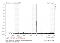
Well, I have not build exactly this amplifier, but have enough experience with almost same topology. In my experience it is always profitable (for resulting sound) to keep high order harmonics amplitude as low as possible. Even if we have some small rise at low harmonics. And, I believe in John's circuit intuition, rather than in pure theoretician's. It has always proven right, to me. Example of real amplifier attached.
Attachments
Last edited:
Hi Pavel,
While I have been playing mainly on the tube side for the last decade+ I agree that what you describe sounds subjectively better.
The debate was if John's inner loop actually does that (reduce high order HD) or not.
Your simulation results and my intuition both suggest that it is so, but I summarised a fair overview of what is presented in this thread.
I have found in practice the same and I find that whenever I push THD down using looped feedback OR distortion cancellation I get more high order stuff and the sound is worse.
Why spoil a beautiful theory with incovenient facts?
Ciao T
Well, I have not build exactly this amplifier, but have enough experience with almost same topology. In my experience it is always profitable (for resulting sound) to keep high order harmonics amplitude as low as possible. Even if we have some small rise at low harmonics.
While I have been playing mainly on the tube side for the last decade+ I agree that what you describe sounds subjectively better.
The debate was if John's inner loop actually does that (reduce high order HD) or not.
Your simulation results and my intuition both suggest that it is so, but I summarised a fair overview of what is presented in this thread.
And, I believe in John's circuit intuition, rather than in pure theoretician's. It has always proven right, to me.
I have found in practice the same and I find that whenever I push THD down using looped feedback OR distortion cancellation I get more high order stuff and the sound is worse.
Example of real amplifier attached.
Why spoil a beautiful theory with incovenient facts?
Ciao T
Why spoil a beautiful theory with incovenient facts?
Ciao T
That's a good one, Thorsten
.Where to meet you, Dresden?
Best,
I find that whenever I push THD down using looped feedback OR distortion cancellation I get more high order stuff and the sound is worse.
Ciao T
In other words: incompetent design
Ciao S
Here are two pictures, one is simulation of IHD for my amp, second is measurement for the same , realized circuit. I found according this simulations quite reliable, if properly used with realistic models and all faults in realization are avoided (PCB, grounding, etc..).
2 PMA
What about posting here Your .cir file?
2 PMA
What about posting here Your .cir file?
Attachments
I’ve used the free Ltspice sim, developed, supported, used internally by a leading analog IC house
Linear Technology - Design Simulation and Device Models
anyone with a PC, Laptop can download run this – Mac users may need Wine
I posted my sims source files, included the Q models on the schematic
I have publicly requested PMA’s models, I think this would be “fair use” for copyright issues
My sims can be inspected for bias points, modified, any test waveform you want to try, tweaking Spice simulation/fft plot parameters
It seems a little premature to move to the exits as it were, muttering “inconclusive, nothing proved...”
when so far "2 out of 3 sims agree.." just not with the inner loop feedback R helping (and only if you count "full" circuit sims, dismissing my simplified model - we use simplified models because they are a lot less work)
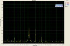
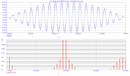
The usual jc3full sim, green v(out)@1 is without inner feedback, yellow @2 trace is with inner feedback resistors
The pic is a little large but I wanted to include the 1K and still have everyone be able to see the higher frequency IMD skirts too
Now is someone going to point out that the inner feedback made the 1 kHz IMD product “better” by 1.5 dB while ignoring the faster decay of the higher order difference "skirt" envelope?
Linear Technology - Design Simulation and Device Models
anyone with a PC, Laptop can download run this – Mac users may need Wine
I posted my sims source files, included the Q models on the schematic
I have publicly requested PMA’s models, I think this would be “fair use” for copyright issues
My sims can be inspected for bias points, modified, any test waveform you want to try, tweaking Spice simulation/fft plot parameters
It seems a little premature to move to the exits as it were, muttering “inconclusive, nothing proved...”
when so far "2 out of 3 sims agree.." just not with the inner loop feedback R helping (and only if you count "full" circuit sims, dismissing my simplified model - we use simplified models because they are a lot less work)
The usual jc3full sim, green v(out)@1 is without inner feedback, yellow @2 trace is with inner feedback resistors
The pic is a little large but I wanted to include the 1K and still have everyone be able to see the higher frequency IMD skirts too
Now is someone going to point out that the inner feedback made the 1 kHz IMD product “better” by 1.5 dB while ignoring the faster decay of the higher order difference "skirt" envelope?
Attachments
Last edited:
its not my score keeping
or is it that you don't think that the models can be shared?
or that maybe we could work out sim setting, potential device bias, test levels, "leveling" assumptions issues if we were using the same models, even in different Spice sw
Folks,
So let me summarise where this whole set of simulations regarding the JC-3's inner loop has left us:
1) We have several simulations that use more modern and arguably by far more linear parts and are more or less similar to the original design. Non have shown either 19 + 20KHz IMD spectrae, 76 + 80KHz Spectra or TIM diagnostic signal waveforms. All Show 1KHz or 10KHz HD only.
2) One Sim shows no appreciable difference between the inner loop connected and not at 1KHz, suggesting to me that the Output Stage transistor models are not very good, as even in Class A an EF2 stage is not THAT low distortion that 40dB+ change in feedback factor for the output stage have no effect whatsoever at lower order HD.
3) Another Sim shows that connecting the inner loop reduces higher order HD at the expense of more lower order HD (2nd to be specific) which would be case if the higher order terms are a mixture of multiplication products between multiple distorting stages and "re-entrant" distortion.
4) A third Sim using supposedly the same software, settings and models shows the opposite of the second sim (3) and was posted after the second one appeared to show that in fact the inner loop works as advertised. It shows that in fact things are as those promoting the superiority of the global loop claim...
Ciao T
or is it that you don't think that the models can be shared?
or that maybe we could work out sim setting, potential device bias, test levels, "leveling" assumptions issues if we were using the same models, even in different Spice sw
Last edited:
Hi,
Why not.
No, sorry, that is not what I noticed. Your sims showed basically "no real difference", based on you wrote...
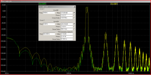
This is 19 & 20KHz? Gosh this looks bad, what is wrong with your sim?
I can barely tell there are two signals!? Is that something that LTSpice does? I expect a rather different picture in my old (and now non-functional) copy of P-Spice. I was considering a switch to LTSpice, but looking at that I better buy an old 2nd hand Laptop to run Win XP and PSpice on...
Ciao T
It seems a little premature to move to the exits as it were, muttering “inconclusive, nothing proved...”
Why not.
when so far "2 out of 3 sims agree.."
No, sorry, that is not what I noticed. Your sims showed basically "no real difference", based on you wrote...
The usual jc3full sim, green v(out)@1 is without inner feedback, yellow @2 trace is with inner feedback resistors
This is 19 & 20KHz? Gosh this looks bad, what is wrong with your sim?
I can barely tell there are two signals!? Is that something that LTSpice does? I expect a rather different picture in my old (and now non-functional) copy of P-Spice. I was considering a switch to LTSpice, but looking at that I better buy an old 2nd hand Laptop to run Win XP and PSpice on...
Ciao T
Hi,
Maybe, maybe not. You would not know...
Maybe I just do not use enough feedback?
Then again, how do I get a stable Amp with 60dB Loop Gain at 100KHz?
Ciao T
In other words: incompetent design
Maybe, maybe not. You would not know...
Maybe I just do not use enough feedback?
Then again, how do I get a stable Amp with 60dB Loop Gain at 100KHz?
Ciao T
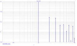
With and without 1meg resistors, lower values are of course without those resistors.We have several simulations that use more modern and arguably by far more linear parts and are more or less similar to the original design. Non have shown either 19 + 20KHz IMD spectrae
Attachments
windowing in fft is a trade off, selectable in Ltspice
Blackman windowing - pushes down the "hair" of spectral leakge "floor", in exchange it widens the lines, takes up 4 "bins" for the windowing skirt to fall to the sim's numerical fft "noise floor"
the sim is only 5x periods of the 1 kHz difference so the Blackman "fattening" of the spectral lines means the overlap doesn't drop to the fft floor, the windowing skirt is ~ 20 dB down from the peak at 400 Hz offset = 2 "bins" for a 5 ms sim
the "points" of the spectral lines are what is relevant - there are no mechanisms generating less than 1 kHz differences in this sim
I chose Blackman rather than the defult becouse I wanted to "look lower" - I could have lengthed the sim but was pushing tol, t_minstepsize to the point of taking 10s of minutes already
Last edited:
I could have lengthed the sim but was pushing tol, t_minstepsize to the point of taking 10s of minutes already
OUCH!
I point out that taking the input stage out of the circuit and estimating its output impedance has a problem, in situ the resistance seen by a current into the high Z node is ~1.6K vs ~1.8k in the two cases due to the global feedback. This can be estimated on the back of a small envelope.
Another problem I noticed is that this is one of those "re-entrant" distortion problems with a cascade of products and is VERY sensitive to the input level, 1dB at fundamental is 10 or so at the 9th harmonic.
- Status
- Not open for further replies.
- Home
- Member Areas
- The Lounge
- John Curl's Blowtorch preamplifier part II