To be honest I don't subscribe to "Belting".
But if that is what you believe in, I'm happy to respect your deeply held beliefs...[/QUOTE]
Not my deeply held belief.
I'm just wondering why it's not one of John's. It's been shown to "work" by the exact same measure other things, such as not using steel chassis have been shown to "work."
It "sounds better."
se
Steve,
Well, if that is what you are doing, have fun.
I wonder if you could explain why reasonably well aged "generic" (e.g. what comes in the box with most cheap gear) cables do not measure like a loopback using RG-223/Mil on HD?
Ciao T
Most cheap gear does not come with RGB/YPrPb or HDMI cables. Do you mean taking the "red-white-yellow" set and using it for HD? In that case I could understand.
Last edited:
Scott,
HD = Harmonic Distortion
Ciao T
Most cheap gear does not come with RGB/YPrPb or HDMI cables. Do you mean taking the "red-white-yellow" set and using it for HD? In that case I could understand. BTW Netflix has an 11min. 24FPS HD video demo up on their instant view server, no info why.
HD = Harmonic Distortion
Ciao T
Not sure why they should have theirs checked, it looks okay. Mine looks very similar on loop back if I use well screened cables that do not use steel center conductors.
The cables with the steel center conductors measured no differently than those with pure copper wires.
se
The cables with the steel center conductors measured no differently than those with pure copper wires.
se
If you can't measure any difference that often is an indicator your test is not sensitive enough.
There are no freaking microdiode effects. I have deliberately add copper oxides to a conductor and after cooling the distortion did not change.
However there are microdiodes the Leprechauns keep them next to the pot of gold.
But Ed you showed pictures of sharp discontinuities in conductivity. The VI curves you posted will rectify (if they really exist).
My misread Thorsten
That's because your test equipment is full of cheap nasty copper, which hides the effect.after cooling the distortion did not change.
But Ed you showed pictures of sharp discontinuities in conductivity. The VI curves you posted will rectify (if they really exist).
My misread Thorsten
The curves you refer too are not microdiodes. Lets be clear that diodes always conduct although it is not linear as per voltage versus current. There is another issue (dead zone) and when I get a bit more along I'll show more.
The issue of oxide's forming diodes was a specific cable test and there were no changes noted at a level at which distortion in the interconnects was noted.
That's because your test equipment is full of cheap nasty copper, which hides the effect.
Yes. Gotta get some ultra pure, single crystal, Ohno continuous cast copper wire.
Cryoed of course.
se
Yes. Gotta get some ultra pure, single crystal, Ohno continuous cast copper wire.
Cryoed of course.
se
Best is unobtanium, then silver (Cyro if you prefer), then the rest. But I haven't tried carbon or some of the other candidates. Really busy.
Why don't you test them?
Best is unobtanium, then silver (Cyro if you prefer), then the rest. But I haven't tried carbon or some of the other candidates. Really busy.
Why don't you test them?
No interest.
se
plain ole plain ole
Actually, since the cheap nasty plain copper hides the effects, Occam's razor suggest if one only uses cheap nasty plain old copper in all things audio, said effects will not be perceived, no?? Then this entire discussion will be moot. same for the steel canard thingie...
Yes. Gotta get some ultra pure, single crystal, Ohno continuous cast copper wire.
Cryoed of course.
se
Actually, since the cheap nasty plain copper hides the effects, Occam's razor suggest if one only uses cheap nasty plain old copper in all things audio, said effects will not be perceived, no?? Then this entire discussion will be moot. same for the steel canard thingie...
A non-magnetic allot to consider is the Monels.
Magnetic properties and machinability of Monels
In a previous job we used them in 8" od, 2" ID and in 30 foot lengths to keep a magnetometer away from the steel pipe we were using.
Also one of the metals with the lowest Q for vibration is Lead, but health and safety is troublesome...
Wrinkle
Magnetic properties and machinability of Monels
In a previous job we used them in 8" od, 2" ID and in 30 foot lengths to keep a magnetometer away from the steel pipe we were using.
Also one of the metals with the lowest Q for vibration is Lead, but health and safety is troublesome...
Wrinkle
Actually, since the cheap nasty plain copper hides the effects, Occam's razor suggest if one only uses cheap nasty plain old copper in all things audio, said effects will not be perceived, no?? Then this entire discussion will be moot. same for the steel canard thingie...
Point taken.
se
The curves you refer too are not microdiodes. Lets be clear that diodes always conduct although it is not linear as per voltage versus current. There is another issue (dead zone) and when I get a bit more along I'll show more.
The issue of oxide's forming diodes was a specific cable test and there were no changes noted at a level at which distortion in the interconnects was noted.
The VI curves would indicate rectification at a proper bias, in many tests this would be indistinguishable from diode-like behavior.
The VI curves would indicate rectification at a proper bias, in many tests this would be indistinguishable from diode-like behavior.
That is an interesting interpretation. I think the dead zone is symmetrical, although it may not be so. I think that any bias turns it on. So if the dead zone were say a volt and you biased it to a volt then a -.1 volt application would be linear down to .9 volts or a .1 volt application would raise it to 1,1 volt. But if you applied -1 volt then the dead zone would reappear until you hit -2 volts or back to zero, so it would be more of an offset to my view rather than a gate (Diode.)
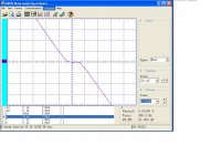
Just as a point of interest, here is a distortion plot of a 1 meter length of RG-174 coaxial cable, which uses a copper-clad steelAn externally hosted image should be here but it was not working when we last tested it.center conductor.
An externally hosted image should be here but it was not working when we last tested it.
The spike at 3kHz is the AP's residual distortion.
se
On the issue of ferromagnetic materials (FMM) introducing audible distortion, I am going with this - thanks for posting. I do believe the AP does not lie. Of course, doing stupid things with the layout are to be avoided, but claiming you can 'hear' when FMM is used in the construction, especially in a small signal environment, seems apocryphal.
That is an interesting interpretation. I think the dead zone is symmetrical, although it may not be so. I think that any bias turns it on. So if the dead zone were say a volt and you biased it to a volt then a -.1 volt application would be linear down to .9 volts or a .1 volt application would raise it to 1,1 volt. But if you applied -1 volt then the dead zone would reappear until you hit -2 volts or back to zero, so it would be more of an offset to my view rather than a gate (Diode.)
As usual I await your tests, 1V "dead zones" would hardly have passed unnoticed till now. You would do well to read up on Paschen's Law before speculating on charges jumping a small gap.
Last edited:
As usual I await your tests, 1V "dead zones" would hardly have passed unnoticed till now. You would do well to read up on Paschen's Law before speculating on charges jumping a small gap.
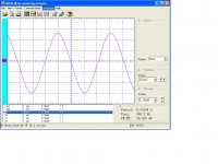
1V is used as an example. For the others here is the curve Scott is referring to.
Attachments
- Status
- Not open for further replies.
- Home
- Member Areas
- The Lounge
- John Curl's Blowtorch preamplifier part II