Mr Simon,
how vague you are. Act of diplomacy ?
I wouldn't want to spoil Linear Audio's next issue!
Scott,
A while back I started on a project to test to see if resistor differences are as important as some claimed.
I then modified it by replacing all of the inexpensive metal film (MF) resistors with ones I had thought were better.
>>>The output bias was increased to improve high frequency distortion near clipping. <<<
I was quite surprised by how much better the amplifier measured with these changes.
Sorry Ed if I am reading this correctly you have made mistake No. 1 you can change only one thing at a time or this can not be called an experiment. Fun maybe, like my work over of a Hafler kit. You will have a hard time convincing me that increasing the bias to 50W a side was not the only real difference that mattered (pretty slight BTW). All the crap resistors stayed.
Well then surely you can imagine a Steinway piano in your listening room. How does what you hear through your hi-fi compare to that?
I don't have to imagine, I have one. It's a M size (5'-7") built in 1927. My aunt started out in life as a concert pianist. She played Town Hall when she was 16. The piano was a gift to her from my grandfather. It's been in my house for about 6 or 7 years. The piano was rebuilt at the Baldwin factory in the mid 1980s when Steinway was going through bankruptcy or it would have been done there.
On may piano recordings of Steinway pianos, I can come very close to the timbre of the Steinway. It has a very characteristic tonal signiture. More forward and warmer, slightly less brilliant than my Baldwin. What modified AR9 can't duplicate is the presence of the piano. This is because of the gross difference between the way the piano radiates sound into space and the way the speakers radiate sound into space. It's a manifestation of geometric distortion of the field. To correct it, I'd have to redesign the speakers from the gound up. Too much trouble and very expensive. But if I were going to put money and effort into it, that's where it would go. Much more beneficial than replacing a preamplifier IMO.
Sorry Ed if I am reading this correctly you have made mistake No. 1 you can change only one thing at a time or this can not be called an experiment. Fun maybe, like my work over of a Hafler kit. You will have a hard time convincing me that increasing the bias to 50W a side was not the only real difference that mattered (pretty slight BTW). All the crap resistors stayed.
Scott,
The test is just for the feedback resistor, that is the variable. The preamble is how I got the test amplifier for anyone who wants to repeat the experiment.
I did not compare the before amplifier to the after. That was not the issue. I do have techniques that can be applied to any amplifier and I used some of them on this one, the idea being to eliminate the objection that the amplifier wasn't good enough to show a difference.
The question is can one resistor change the sound of the amplifier when used as the feedback resistor?
So I had an improved amplifier with one switchable variable, the feedback resistor.
One feedback resistor was carbon comp the other a metal film. I trimmed the carbon comp into matching the metal film with parallel carbon film resistors. So both values were 33.25K Of course the carbon comp will change a bit with ambient temperature, but I want to reduce the problem with the gain change ruining the results.
I used all six positions of the switch to select the one in use.
At first I heard clearly heard changes that did not correspond to just changing resistor types, so I took some measurements.
They showed an obvious increase in the noise floor. BUT IT DID NOT TRACK RESISTOR TYPES!
Attachments
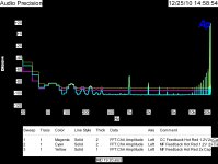
On plots like these you have to "un-rms" out the noise floor or the peaks can be off.
Thanks for the tip. Will use it in the future.
But the problem here turned out to be the switch noise!
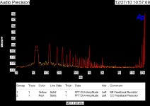
So as JC mentioned silver switches work best with wiping action. So a bit of cleaning and I ran 19 & 20khz IM distortion plots to compare the two types.
If anyone can see a difference between the two types please point it out to me as I do not on this type of measurement. Note the scale does not show the full input signal.
More after lunch. Converting the plots is slow going.
Attachments
Last edited:
Thanks for the tip. Will use it in the future.
But the problem here turned out to be the switch noise!
So as JC mentioned silver switches work best with wiping action. So a bit of cleaning and I ran 19 & 20khz IM distortion plots to compare the two types.
If anyone can see a difference between the two types please point it out to me as I do not on this type of measurement. Note the scale does not show the full input signal.
More after lunch. Converting the plots is slow going.
You mean you haven't replaced switching in the signal path with mercury wetted relays? And you people call yourselves high end?
I'm sorry, but that has yet to be established as fact.
se
You are welcomed to wait for proofs.
I know what I hear.
You are welcomed to wait for proofs.
I know what I hear.
So do those who put photographs of themselves in their freezers.
se
So do those who put photographs of themselves in their freezers.
se
What bothers you here?
What bothers you here?
People making unsubstantiated, objective claims of fact.
se
What bothers you here?
Claims made with plausibility and certainty inversely proportional to evidence, perhaps.

So do those who put photographs of themselves in their freezers.
se
I do that in the hot summer months, and you know what, I feel cooler.
I do that in the hot summer months, and you know what, I feel cooler.
HA!
se
So do those who put photographs of themselves in their freezers.
Imprints of others often are more beneficial.
With a lot of money spent on interconnects, little may remain for the real McCoy. (some fancy cheap as sheit off an industrial reel)
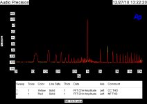
Attached is the THD comparison of metal film vs carbon comp. The only notable difference is in the third harmonic distortion. It is greater than would have been predicted by my resistor measurements but probably not large enough to stand out
Did you repeat the measurement after going back to the metal film?
se
Imprints of others often are more beneficial.
What, you mean like some form of voodoo doll audio?
se
People making unsubstantiated, objective claims of fact.
Claims made with plausibility and certainty inversely proportional to evidence, perhaps.
I know what I hear and there is nothing I need to prove to anyone.
Did you repeat the measurement after going back to the metal film?
se
Many many runs of each.
- Status
- Not open for further replies.
- Home
- Member Areas
- The Lounge
- John Curl's Blowtorch preamplifier part II