Let me just say that if we take a GENERIC inverting integrator of either RL or RC configuration, the input pulse will be pre-filtered by the passive network, BEFORE it reaches the input stage of the op amp. Therefore, you are not performing the 'miracle' that you think you are doing with your op amp design. Of course, if you only amplified the coil's output, then you would be on to something, and I would thank you for it. However, from my position, your 'real' impulse at the input of any op amp you might have chosen is 2 times slower than my TIM(30,30) pulse although my TIM(30,30) would turn back into a risetime limited square wave, if it went into YOUR inverting integrator before it reached your op amp input, which would be quite easy for you to handle.
Why don't you try to do what you are successful at doing, with a non-inverting quasi integrator, or a typical phono stage like you showed on your graph, and see what happens?
Hi John,
I certainly agree with you that most op amps are happier in many regards when operating in the inverting mode, and that sharp edges in the input signal don't get to the input differential pair as badly, due to the RC filter you describe in the inverting integrator configuration. There is also the matter of little or no high-frequency, sharp-edged common mode applied to the op amp.
This does not, however, make it impossible to get low TIM in an op amp of high quality using feedback in a non-inverting configuration.
BTW, these discussions bring back to mind the use of passive RIAA equalization that has often been preferred as rendering higher quality. In such a case, of course, the fast edges are LPF'd without stress on an amplifier. The use of a passive RC for the high-frequency turnover followed by an integrator-type low-frequency turnover is also a good approach that still keeps fast transients out of the following amplifier.
Of course, there still remains the first buffer stage, which must deal with the fast edges that may come from the cartridge. At least this stage then only has one job to do. It must be a chunk of gain with low noise that has very low distortion, even at high frequencies at fairly high amplitude, and must be very resistant to EMI from all sources. This is particularly important for the first stage in moving coil preamplifiers.
Cheers,
Bob
Of course, an INVERTING input will work. Then, how do you put the optimum resistive loading on the MC phono cartridge? I have generated whole designs around this input summing concept, but they failed to sound 'right'. This is bypassing the problem, but I found 35 years ago, that you could NOT bypass the problem this way, and still get the best sound from the majority of MC phono cartridges. If you don't believe me, try some listening tests yourself, making an A-B switch that will change the input from almost Zero ohms to 100 ohms, for example.
This is obvious. But input buffer would enable individual load setting.
BTW, I have sold 2 commercial MC phono preamp designs in last 2 years. The optimum load is set by jumpers, from 5 res. values.
Yes, this is a better option.
Is there any reason why NOT to use the inverting topology for MC phono preamp? The low input resistance for low noise requirement would be fulfilled, as most MC cartridges enable loading like 50 - 100ohm.
Hi PMA,
I think that an inverting feedback structure where the load resistor for the MC cartridge goes to the virtual ground of the inverting input of the amplifier would be risky and would provide for less flexibility in loading the cartridge and achieving desired voltage gain. I would worry about having the fairly low-Z inverting amplifier return go all the way back through the moving coil cartridge itself, especially since the impedance of that path will be relatively unknown at high frequencies, is likely inductive, and may have destabilizing resonances.
My vote is for a very good low-noise non-inverting amplifier with moderately high input impedance and whose gain is maybe 20 dB. Cartridge loading should then be independent. The amplifier should be very robust in the presence of EMI and high frequencies.
While low noise is very important, it is not the be-all and end-all for sonic quality. Noise needs to be low enough. Linearity and robustness to high frequencies and EMI should not be compromized in an unnecessary quest for the lowest achievable noise. The use of JFETs should not be ruled out for this reason.
Cheers,
Bob
For my MC cartridge loading, I will use a remote controlled 10 turn wirewound triple pot of 5K ohms, that will switch from there. Already designed into my latest preamp. I want resolution to 1 ohm or so. The resistor value will come up on a video screen and can be stored for future setting. We shall see whether we can tell that much difference or not, especially with $5,000 and above phono cartridges, like Joachim uses.
Hi Bob,
how about low-noise buffer + inverting topology, that I mentioned in the next post.
Regards,
Hi PMA,
That should work fine. However, I would also consider achieving the HF turnover with a passive shunt capacitor in the middle of a divided inveter-stage input resistor; then all that is needed of the inverting equalizer network is the LF turnover. However, with this topology we end up with a net inversion in the preamplifier, which may be undesirable.
Cheers,
Bob
Bob said:The use of JFETs should not be ruled out for this reason.
I thought the way Dennis Colin used a two paralleled JFETs in a common source amplifier, with the output driving the inverting input of the AD797 directly was really creative. This way the output is connected to virtual ground, compensating for the miller effect.
I think this first stage had a gain of about 100, as I remember.
However, with this topology we end up with a net inversion in the preamplifier, which may be undesirable.
Cheers,
Bob
Hi Bob,
I would definitely add the inverting output stage with gain -1x. I would never left the circuit with 180° phase.
Regards,
.An open question to all, but probably especially for Scott :
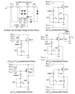
Is there a simple method for DIYers to measure the frequency dependent Ciss and Crss values of JFETs and MOSFETs ?
There are 2 figures in the Freescale AN211A, but with no description at all.
Thanks in advance,
Patrick
Here's a better set of test jigs. Just substitute a decent hand held C meter and with careful zeroing you should be able to get pretty close. For the JFET's you normally use measuring Cgd = Crss should be enough . Since they are symmetrical Cgs = Cgd and you should be able to read the values off of the Crss vs V graph for any operating point.
Attachments
Last edited:
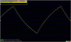
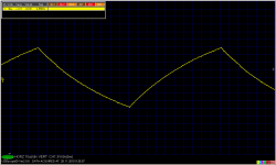
Someone here wanted to see a shape of output voltage of RIAA preamp waveform when input is 5kHz square. The input wave has rise times 200ns. Here you are:
Edit: full scale 5kHz square added
Edit: full scale 5kHz square added
Attachments
Last edited:
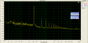
Looks like surprisingly high levels of ultrasonic noise. Is that real?
It is no ultrasonic noise, BUT 8-bit A/D digitization of the scope (only 255 levels per full screen scale). You measure the same from generator only. Sometimes I am very surprised what I read here.
- Status
- Not open for further replies.
- Home
- Member Areas
- The Lounge
- John Curl's Blowtorch preamplifier part II