Frequency and time domain are interelated in FFT analysys. An exception is noise. How about a train of halve sinewaves for testing of amplifiers that have only positive or negative polarity ? An FFT analyser could not make sense of that.
Why not? Even noise has a Fourier transform- we talk about 1/f, for example. The signal you drew looks roughly periodic, and if you select any finite time interval for sampling, ANY signal can be treated as periodic, with the period being the sampling interval.
In a mini summation of audio design, we have found that negative feedback should be limited or avoided, if possible, and if used, one should at least try to use the most linear circuits possible, including adding extra parts to IC's in order to make them more open loop linear, if necessary. It would appear that you want the feedback to do as little as possible, so that it does NOT show itself in another form, such as frequency modulation.
It might be pointed out that the 'topology' of the 'Otala' amp was pretty good, we had designed better topologies, in the USA, but where we went astray was in the AMOUNT of feedback used. 20dB once again seemed to be the magic number. More, and you got lower open loop bandwidth, lower slew rate, even if you got better IM and harmonic distortion specs. At first, we thought that TIM was the only culprit, but we found out later, that even amps with 100V/us, could still sound marginal, IF the open loop bandwidth criterion was severely restricted. You see, it is relatively easy just to remove load resistors from the first stage and substitute current sources to get 100-10,000 times more open loop gain. However the open loop bandwidth will diminish correspondingly. This is where we get today's IC op amps. It seems to change the sound, even if other parameters are improved, and slew rate is maintained. This is the puzzle at hand.
As seen in this link the feedback needed to be increased to 30dB before the Otala design started to perform and sounded good:
Story of "Otala" Amp
A small series of the "Otala" amp sold in the mid eighties by Terje Sandstrøm was upgraded with JFET input transistors, improved power supply and if I remember correctly 40dB feedback and was the best sounding version of the "Otala" amplifier.
John - you haven't said much about layout design (in particular grounding) so far in this thread. Do you pay a lot of attention to it? The reason I ask is I've been playing around with an active speaker and got a substantial improvement in clarity just by rejigging the grounding, its gone from being 'upper mid-fi' to high end (within the limitations of the drive units) in my estimation. Have you had any similar experiences with changing a design's grounding/decoupling?
"Traditional audio measurement approaches are based in the frequency
domain, using FFT technology and the steady state test tones it relies
on."
As soon as you see that, you can be well prepared for what's ahead.
I was particularly taken by the comparative spectrographs on the top of page 4, clearly showing the "tweak" setup to have more HF noise and hash. That, of course, is not mentioned....
SY, I can't read the scales on those graphs and they don't appear amenable to enlargement with any clarity BUT the hash and noise is clearly lower in level on the tweak setup at least to my eyes ,though what is ther appears hashier in nature.
Is there anything in the type of testing explained here do you think?
http://www.nordost.com/downloads/New Approaches To Audio Measurement.pdf
The article is marketing and has inconsistencies but the type of testing reported may have some merit I suspect.
I saw their presentation at RMAF last year. I was underwhelmed to say the least. I don't think it will stand up under scrutiny and there were myriad procedural flaws in their process. If they get rigorous in the test process and publish enough that the tests can be duplicated we may learn something. What I saw was marketing hype with no substance.
do you have the service manual in pdf on the 5173 im trying to do a performance test
Which 5173? Quan-Tech?
Based on my experience, I cannot support the idea that feedback should be avoided as a rule.
If the feedback was closed around circuit with very linear and very fast JFET input stage, high current VAS, and high idle class A output stage, high OLG corner, I have not found any sound degradation even with 60dB feedback (in a preamp). On the contrary, it sounded 'better' than no feedback and low feedback designs with higher distortion. IMO it is very difficult to express any general statement about contribution or sound degradation by feedback, it is strongly circuit dependent. I do not believe in the PIM or FM theory, as it has never been proven for a very linear and very fast circuit. uA741 measurements are not any proof, this was swept into a historical dust bin. We do not work with 0.5V/us circuits, but >100V/us circuits in link stages.
If the feedback was closed around circuit with very linear and very fast JFET input stage, high current VAS, and high idle class A output stage, high OLG corner, I have not found any sound degradation even with 60dB feedback (in a preamp). On the contrary, it sounded 'better' than no feedback and low feedback designs with higher distortion. IMO it is very difficult to express any general statement about contribution or sound degradation by feedback, it is strongly circuit dependent. I do not believe in the PIM or FM theory, as it has never been proven for a very linear and very fast circuit. uA741 measurements are not any proof, this was swept into a historical dust bin. We do not work with 0.5V/us circuits, but >100V/us circuits in link stages.
Last edited:
I tend to use negative feedback in large quantities in my 'normal' designs. For example, the Parasound JC-1, JC-2, have lots of negative feedback. Are they the VERY BEST that I can do? No. Recently, I was asked to make a virtually 'perfect' 10W amp. There, I would NOT use global negative feedback, and my open loop bandwidth would have to exceed 100KHz. Impossible? Maybe. Still, that is what I would attempt to do.
For more power, perhaps 100W, I might try for a 20K open loop bandwidth, and 20dB of feedback, based on previous experience. However, for 400W into 8 ohms (800W into 4 ohms) I need lots of negative feedback in order to meet specs. That's life, and I accept it. Perfection is relative, and one solution is impractical.
For more power, perhaps 100W, I might try for a 20K open loop bandwidth, and 20dB of feedback, based on previous experience. However, for 400W into 8 ohms (800W into 4 ohms) I need lots of negative feedback in order to meet specs. That's life, and I accept it. Perfection is relative, and one solution is impractical.
I tend to use negative feedback in large quantities in my 'normal' designs. For example, the Parasound JC-1, JC-2, have lots of negative feedback. Are they the VERY BEST that I can do? No. Recently, I was asked to make a virtually 'perfect' 10W amp. There, I would NOT use global negative feedback, and my open loop bandwidth would have to exceed 100KHz. Impossible? Maybe. Still, that is what I would attempt to do.
For more power, perhaps 100W, I might try for a 20K open loop bandwidth, and 20dB of feedback, based on previous experience. However, for 400W into 8 ohms (800W into 4 ohms) I need lots of negative feedback in order to meet specs. That's life, and I accept it. Perfection is relative, and one solution is impractical.
John,
There is much talk here about PIM, wide OLBW etc, however I don't see
much discussion about distortion versus frequency profile which is one
result of the OLBW and amount of NFB used.
It is my observation and experience that amplifiers with a flat distortion
versus frreq characteristic sound better than ones with rising distortion
at higher freq, even where the absolute levels are lower.
Ref to two images below. Both amplifiers won Stereophiles highest accolades
WRT subjective sound quality. Both have no loop FB. The distortion levels
are moderate in one and quite high in the other but they both share a very
uncharacteristic (for an amplifier) flat thd level vs freq respone.
I agree with Putzeys on this one, if you are going to use FB, use tons of it
and get rid of -all- distortion right up to 20kHz, which most power amplifiers
dont come close to, or make it flat in level through the audio band.
cheers
T
Attachments
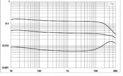
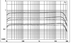
Both measurements are using high frequency rolloff filters, as the distortion will usually rise above 10KHz, if only because of added non-linear capacitance that will come to dominate the nonlinearity, at least in solid state.
I personally think that a flat distortion response is a good thing. IF not, then take the worst case, that is usually above 10KHz.
I personally think that a flat distortion response is a good thing. IF not, then take the worst case, that is usually above 10KHz.
Generally speaking, a flat distortion response, at least to 10KHz, shows a high open loop bandwidth, with either open loop or feedback. More negative feedback would probably be OK, IF we could keep these flat distortion curves, just reducing them with the application with MORE feedback. Alas, that is almost impossible, because for a given gain bandwidth, set by the actual devices used, their operating current, etc., we LOSE open loop bandwidth in order to increase low frequency feedback. In fact, above 10KHz or so, the feedback is about the same with any equivalent amplifier design where current sources replace load resistors, for example. If we could keep the open loop bandwidth to 10KHz or so, we would be way ahead of the curve. Even my best high power designs only have an open loop bandwidth of 4KHz, at the moment, and I am hard pressed to improve it. Still, 4KHz is a lot better than 40Hz, or less, used by many op amp and power amp manufacturers.
Making a direct comparison between my HCA-1000 and the Otala amplifier, the Otala amp sounds better, even though the HCA-1000 measures better (40+dB of feedback) and the Otala has only 20dB of feedback, BUT it has a higher class A range, because it has more idle current, and it has 20KHz open loop bandwidth. I use both, almost every day, with the same brand of loudspeaker, (Sequerra) and I stand by my opinion.
Making a direct comparison between my HCA-1000 and the Otala amplifier, the Otala amp sounds better, even though the HCA-1000 measures better (40+dB of feedback) and the Otala has only 20dB of feedback, BUT it has a higher class A range, because it has more idle current, and it has 20KHz open loop bandwidth. I use both, almost every day, with the same brand of loudspeaker, (Sequerra) and I stand by my opinion.
One test that 'should' work is the so called DIFFERENCE TEST. This is where you subtract the output from the input, while running a musical signal, and note the difference.
Well, I happen to be a minor expert doing difference testing, having done hundreds of tests where we were just going to analyze a SINGLE CAPACITOR. In order to get a difference down below .01%, we had to use either teflon or polystyrene. Think of all the distortion sources in an entire amp, AND its intrinsic delay! If difference testing worked then I presume that Quad and Hafler are virtually perfect. My experience is that they are not.
Well, I happen to be a minor expert doing difference testing, having done hundreds of tests where we were just going to analyze a SINGLE CAPACITOR. In order to get a difference down below .01%, we had to use either teflon or polystyrene. Think of all the distortion sources in an entire amp, AND its intrinsic delay! If difference testing worked then I presume that Quad and Hafler are virtually perfect. My experience is that they are not.
...as the distortion will usually rise above 10KHz,
John, please don't jump to the conclusion that they are automatically using filters to get that response. The whole point of Terry's post was to point out that it does not have to 'usually' rise. My (limited) experience suggests that designs with a flat THD / f response can perform remarkably well compared to those with THD that rises with frequency.
I understand that Lamm makes this flat response a design goal in their line stages.
Terry, which amps were they?
One test that 'should' work is the so called DIFFERENCE TEST. This is where you subtract the output from the input, while running a musical signal, and note the difference.
Well, I happen to be a minor expert doing difference testing, having done hundreds of tests where we were just going to analyze a SINGLE CAPACITOR. In order to get a difference down below .01%, we had to use either teflon or polystyrene. Think of all the distortion sources in an entire amp, AND its intrinsic delay! If difference testing worked then I presume that Quad and Hafler are virtually perfect. My experience is that they are not.
I am sure the difference method works.
BUT the other camp would always require to equalize bandwidths and frequency responses of subtracted channels to identity. They argue by phase shifts.
Well - I am pretty sure that this is the wrong practice. If we modify 200kHz, fast circuit to something like 20kHz -3dB response, I am sure we modify reasons why different circuits sound different as well. It is almost impossible to separate 'linear' and 'nonlinear' issues, they are tight bound together. Again, as in case of controlled blind tests, our two camps would not find agreement.
One test that 'should' work is the so called DIFFERENCE TEST. This is where you subtract the output from the input, while running a musical signal, and note the difference.
Well, I happen to be a minor expert doing difference testing, having done hundreds of tests where we were just going to analyze a SINGLE CAPACITOR. In order to get a difference down below .01%, we had to use either teflon or polystyrene. Think of all the distortion sources in an entire amp, AND its intrinsic delay! If difference testing worked then I presume that Quad and Hafler are virtually perfect. My experience is that they are not.
In the classic difference test one tries to compare the input to the output. I prefer to use two amplifiers, one connected to a resistor typically 32 ohms, and the other drives a loudspeaker.
This shows how the effect of the load!
- Status
- Not open for further replies.
- Home
- Member Areas
- The Lounge
- John Curl's Blowtorch preamplifier part II