SY, as a moderator, yourself, would you like to fire up the HP3581 in your possession, and look at how the meter responds to random noise at different bandwidth settings? You might be able to break this 'stalemate' and we could all learn something new.
John, let go please. There's nothing to learn from this exercise.
Not to appear rude, Syn08, but we were addressing the measurement of noise with the HP3581 Wave Analyzer. I also have an HP3562(3) FFT based analyzer, but that is not what Ikoflexer was referring to, as he apparently doesn't have an HP 3562 to measure with, he has an HP3581. Some test equipment has a more limited setting range than other equipment, and this is the problem that I am addressing.
Everyone, it should be clear that we are trying to address the problem of measuring noise coming from different sources. The Norton equivalent Zener has been measured, in order of magnitude, at least. The LM329 Zener diode substitute, may be measured in future, although the graph of noise vs frequency already exists in the app note. The biggest problem is worst case, and its probability with this device, since the device could be more than 10 times noisier than typical, yet be within spec.
In any case, either approach could be used to establish a low noise reference. I leave the details to the individual designer.
In any case, either approach could be used to establish a low noise reference. I leave the details to the individual designer.
syn08, I'd hate to make you work just to satisfy my curiosity. Please don't worry about it if you don't think it's worth it. If you do measure though, others might find this exercise very helpful. If indeed the lm329 has a mean X and variance Y noise, then that's an important fact to take into consideration for the regular DIYer who doesn't have the necessary measurement instruments to make sure they got the "typical" lm329. As I said before, horses for courses.
Also, syn08, I don't put much weight on "absolute" value measurements. Is there such thing? One can get very picky about such things and demand mean and variance, instrument calibration, etc. AFAIC what I was trying to do with the scope is relative measurements, for comparison purposes. Perhaps I should omit the units when reporting. My scope self noise, or whatever you'd call it, shows as a flat line of perhaps a few micro volts when on 100uV/div settting. Relative to that, the jfet+R reference shows clearly a wiggly trace, with peak-to-peak values as I mentioned before. If I add a capacitor in parallel with the resistor, the wiggly trace becomes flat but thicker than a when nothing is measured with the scope.
Now, your point b) don't know the bandwidth. No need for that in relative measurement; I'll just choose the wave/wiggle with the larges peak-to-peak value. As I said, no paper gets published here, I just want to compare the waves that one component shows on the scope, with the waves the other component makes. This also addresses your point a) hard to estimate average value. One can compare max peak-to-peak as well, not only average.
What I'm saying is, one can directly compare two devices this way if the instrument has enough resolution to show their relative noise difference. I agree with anyone who says that this method does not give any absolute values.
Ikoflexer, at the risk of 'butting in', your measurement is reasonable, if not very accurate. However, if you found real improvement by adding the cap across the resistor, why not just use it and be done with it? Of course you can add an RC of equal value to the LM329 and get good results there too. My point is that it is not cheaper or better to do so. In fact, it can be limiting, as the Zener substitute is only a fixed voltage and some way normally has to be used to increase it, in order that it can give higher voltage power supplies.
Salas, the 1000uF cap should do no harm, but it might not do any significant good either. This is because you are trying to filter from a virtual voltage source, rather than having a resistor to work against. This doesn't work very well, because a 10 ohm source (for example) is 100 times less efficient with a cap, as a 1000 ohm source would be. RC is the filter, not just C. Therefore, a 10uf cap with 1K in front, is equal to 1000uf with 10 ohms in front. I hope that this is clear to everyone. It is a usual oversight, and I see it all the time, even with the engineers that I work with, on occasion.
Salas, the 1000uF cap should do no harm, but it might not do any significant good either. This is because you are trying to filter from a virtual voltage source, rather than having a resistor to work against. This doesn't work very well, because a 10 ohm source (for example) is 100 times less efficient with a cap, as a 1000 ohm source would be. RC is the filter, not just C. Therefore, a 10uf cap with 1K in front, is equal to 1000uf with 10 ohms in front. I hope that this is clear to everyone. It is a usual oversight, and I see it all the time, even with the engineers that I work with, on occasion.
Measuring noise with a scope is extremely imprecise and that's because a) it's not easy to estimate the average value b) you don't know exactly the bandwidth and c) you don't know the scope Y amp noise.
I'll do some measurements myself tonight (time permitting). I have all the needed devices and a 89410A plus a 3562A to compare with. I can do 0.001Hz RBW (overnight) without any "bouncings", in fact all the noise measurements on my web site are at 0.1Hz RBW or less.
Hey syn, thanks for bothering. Will you do the 4 generic leds with big cap bypass fed from a GR or BL CCS too while at it? Cheers.
Salas, the 1000uF cap should do no harm, but it might not do any significant good either. This is because you are trying to filter from a virtual voltage source, rather than having a resistor to work against. This doesn't work very well, because a 10 ohm source (for example) is 100 times less efficient with a cap, as a 1000 ohm source would be. RC is the filter, not just C. Therefore, a 10uf cap with 1K in front, is equal to 1000uf with 10 ohms in front. I hope that this is clear to everyone. It is a usual oversight, and I see it all the time, even with the engineers that I work with, on occasion.
That is why I will go 10-20x the cap usual moderate value when with the relatively low impedance 100-200R LEDs Vref. Got that. Thanks.
P.S. The LEDs are going to be far less governed by the IDSS Tc wandering of the Jfet CCS feeding them than when feeding a resistor, their Vf is much stiffer to plateau current variation, so I think this is a good thing for keeping the cascode base Vbias the same for both channels at all times and with different nearby heat radiations to the Jfet CCS per side. I mean I don't know it yet, I just presume.
OK, so how about this. My concern as an average DIYer is a good Vref solution. We are considering so far the following:
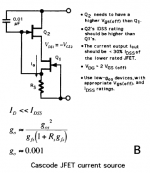
1. the Norton zener, i.e. an appropriate jfet in series with an R||C filter. Please note that a resistor in parallel with a capacitor DOES act as a band filter IF it is being fed (in series) with a current source. That's the job of the jfet. The CCS can be improved by two cascoded jfets, but they have to be chosen appropriately (see figure). I already posted a few pages ago a list of jfets which are recommended in that book for this purpose.
Advantages: flexibility in Vref value. With suitable C across R, low noise (how low to be established). Cheap.
Disadvantages: to be determined.
2. lm329 or equivalent low noise voltage reference.
Advantages: low noise, less affected by temperature variations, specifically created for this purpose.
Disadvantages: large variation in noise specs (John pointed this out), but noise can be reduced with an RC filter.
3. LEDs in series, possibly with a capacitor across them. Clearly some LEDs have less self noise than others. Issues that are not IMHO well addressed: unless one can measure it, how can one choose from the multitude of LEDs? How effective in reducing noise is the capacitor across them.
4. Zener reference, possibly with RC or C filter.
IMHO it would be best if we could characterize more completely these four solutions in terms of what they offer and what they lack, instead of claiming one is best. If the solutions are well defined then everyone can choose what is "best" for them individually.
Please correct any issue I might have gotten wrong here. Comments are welcome.
Attachments
Last edited:
SY, as a moderator, yourself, would you like to fire up the HP3581 in your possession, and look at how the meter responds to random noise at different bandwidth settings? You might be able to break this 'stalemate' and we could all learn something new.
How about if I do that just as a participant, a measurement geek, and someone interested in low noise design?

Have you checked your pm? I sent you one a few days ago. You should have a little notification in the upper right hand corner.
OK, so how about this. My concern as an average DIYer is a good Vref solution. We are considering so far the following:
1. the Norton zener,
Disadvantages: to be determined.
- High output impedance. Therefore, poor load and line regulation.
- Poor temperature behaviour. Biasing at zero tempco not necessary possible or reproductible.
If temperature stability is required. All that has to be added is a series resistor between the gate and source of the jfet, of the proper value to give about .75-.8V Vgs. This will give 0 tempco. The Id will change from Idss, droppng from 8ma to 4 ma for example with a suitable J203 jfet.
Reference to this is pp.103-104 Toshiba 'Small Signal Transistor' manual 1992
Reference to this is pp.103-104 Toshiba 'Small Signal Transistor' manual 1992
SY, lots of luck, and if you want to buy the unit, you can have it at 1/2 my original cost. (to me, not the original cost of the unit, new. Big difference)
Be happy to. Drop me an email.
A member did exhaustive testing a while ago on the various noise levels from using various LEDs as a voltage reference for CCS use. The end result was that the garden variety, cheap red LED was the lowest in measured noise, the low voltage drop variety. The high efficiency LEDs were noisier, as well as blue and UV LEDs. These measurements where not bandwidth limited, so the measurements do not translate into standard nV / rt Hz type values. However, they are perfectly valid in as much as they identified the least noisy LEDs to use. Like anything else, "build the darn circuit and measure it".
For me, I tend to use a BJT and red LED to build a current source / sink. If you couple the LED to the transistor case, the very similar temperature coefficients allow a very stable current over a wide temperature range. The BJT can be cascoded for higher impedance as well (several Meg. are possible). At the moment, I am experimenting with some J-Fet self biased designs that Walt Jung was kind enough to suggest. My earliest efforts have convinced me that I know very little about using a J-Fet properly this way. I'll keep trying, but the two challenges are temperature stability and VDS stability. I can't seem to attain both at the same time yet.
Hi John,
Both you and syn08 are pretty smart guys. Just accept it and move on.
Now, to answer your bouncing needle question. The answer is pretty easy to come to. Simply connect a good bench meter to the output of your 3581A. I don't know whether you get an AC or DC level output from the 3581A, probably DC knowing HP. Simply set the filtering and sample rate to a level appropriate to capture as much peak information as possible. I'll use an Aglilent / HP 34401A as an example. Allow the meter to capture a number of samples, then call up the average value from the menu. Your accuracy will increase as the number of samples increases. Done. Now you have solved your bouncing needle issue, and increased the accuracy of your reading at the same time.
This process will weight the peak values properly, as opposed to filtering them out. The process of averaging will decrease peaks both high and low, but at least they will affect the measurement as they should.
In the old days, one was expected to connect the 3581A to a chart recorder and let it run. So if you only had that, you'd simply average the values on the paper chart. That's pretty much what using the average feature on a good digital meter will accomplish.
So, "back in the day", how did you perform this task? Did you simply avoid using windows that small, or did you use a 3580A? I have a 3580A I need to repair. I expect it will be just the right thing to look at normal power supplies with. I do use the 3 Hz window on my 3585A for that same thing right now.
-Chris
Hi John,
Better VDS stability comes with lower values of drain current compared to IDSS. The tempco may not be such a difficult thing to deal with, and possibly may even be compensated for in some way.
Right now, I'm pouring over the "Low Power Discretes Data Book", by Siliconix, 1989. Any other information source would be appreciated. I have read over Walt Jung's "Sources 101" a couple times already.
-Chris
Something everyone around here (Toronto, Canada or even the service sector) has been searching for, but never finding. That's any year! Even a PDF (from anywhere) would be great!Toshiba 'Small Signal Transistor' manual 1992
Better VDS stability comes with lower values of drain current compared to IDSS. The tempco may not be such a difficult thing to deal with, and possibly may even be compensated for in some way.
Right now, I'm pouring over the "Low Power Discretes Data Book", by Siliconix, 1989. Any other information source would be appreciated. I have read over Walt Jung's "Sources 101" a couple times already.
-Chris
John,
Apart from the incoming noise, a 10uf with a 1k resistor as you know can actually be noisier than 1000uf with 10 ohms if the part selection is wrong. A wrapped film capacitor is quieter than a stacked film which is about the same as an electrolytic. The larger case electrolytic capacitors such as BC are quieter than the miniature case ones.
Of course the resistor needs to running cool and should not be a carbon composition but a decent deposited film. The end cap connection on the film resistor needs to be unstressed by the mounting technique or else it may become noisy.
But then you as you often mention you use three stages, the last one to touch the power uses a polystyrene capacitor, probably one of the quietest types.
ES
Anatech, why not just use the good bench meter, like an ST or HP, and just filter it at 10KHz with a 6 dB/octave rolloff filter? That appears to be what NS did when they characterized the device. Adding yet another meter just confuses the situation, further.
When I was working at the Ampex Audio Department, designing analog tape recorders, 41 years ago, I used an HP wave analyzer that was overdamped with an added capacitor across the meter itself. Then, with log graph paper, I plotted by hand, the overall noise and its changes with frequency, across the entire audio bandwidth, and sometimes, beyond. That method was slow, but it was accurate enough, and still readable today.
The HP3581 does work OK with a graph recorder, and I have sometimes used it, but it is also slow, and my B&K Graph recorder doesn't have the paper width to make it as readable as the old method, which I prefer.
In this case, we expect essentially flat response above 100Hz to at least 10KHz, so why not have the slightly greater than 10KHz bandwidth measured directly with a quality AC voltmeter, again like HP or ST, or B&K, etc?
Last edited:
Glancing over the Toshiba notes again, I found a serious oversight that I made. You have to subtract .7-.8V from the Vgs (off) and use that voltage to bias the device This makes it MORE difficult to calculate. I will have to work on it, but it may be difficult to do with just any jfet, and get something useful. For example, a 2SK170 can never be TC zero, because its pinch off voltage is too low. Interesting problem.
Therefore for Zero TC, stick with a Zener equivalent reference. Everybody else, it doesn't matter that much, anyway.
Therefore for Zero TC, stick with a Zener equivalent reference. Everybody else, it doesn't matter that much, anyway.
Anatech, why not just use the good bench meter, like an ST or HP, and just filter it at 10KHz with a 6 dB/octave rolloff filter?
Because it would require a 7 1/2 digit instrument. Measuring 50nV/rtHz*100=5uV of noise is not simple to do on a wideband basis, you need a fully shielded and guarded setup.
A sound card set to a small RBW will do a good job, though.
- Status
- Not open for further replies.
- Home
- Member Areas
- The Lounge
- John Curl's Blowtorch preamplifier part II