quote
Any off-centering (which the servo would do) would place the pair in a less linear region.
unquote
Jan, surely wha t you would do here is simply move it along the bias line (I am not talking about a gross mismatch here).?
Anatech,
I am using 4 bipolar input devices on my amp and my source and speakers are quite good - I don't pick up the brittle sound you mention. Betas were matched on a meter to within 10%.
Bonsai said:quote
Any off-centering (which the servo would do) would place the pair in a less linear region.
unquote
Jan, surely wha t you would do here is simply move it along the bias line (I am not talking about a gross mismatch here).?
[snip]
Bonsai, as you know, that bias line is that familiar S-curve where the center is the most linear. Move it off-center and you go to a less linear part. I have the same opinion as you, that the difference would be very small, but don't have any hard data, just opinion.
I wouldn't think it would make such a big difference because it is a relatively smooth non-linearity and feedback is very good at making that all but disappear anyway. But it is measureable in the even harmonics.
jd
yes, I have.anatech said:Hi Andrew,
Have you ever tried to measure beta to compare how close Vbe measures? Just curious. I have, as mentioned above. I would say that matches in beta area subset of matches in Vbe.
I find little correlation, although others have posted the opposite view. Maybe we test differently.
I think Vbe and Vgs are far more important, then I select for a close match of gain (hFE) or transconductance (gfs). BUT ALWAYS at operational quiescent currents.
I am not usually able to test at operational Vce nor Vds, due to dissipation limitations, but I doubt our disagreement is due to this lack of ability.
As an aside I used to measure hFE first and then try to select similar Vbe from the close batches. It was a complete waste of my time.
The Vbe matches could come from any hFE batch.
I now test Vbe first. Batch them according to this parameter.
The slight problem with this is that the next amplifier may run at a different current and that initial selection must be rechecked at the new current.
This spells out the difference in testing techniques that we use.anatech said:In tested incoming parts for grading, I have seen that when beta matches, so does Vbe. Of course, Vbe is always within a few mV anyway, so I don't see this as a valid measure to grade parts on. AndrewT and I disagree on this basic point. The current sharing is better when matched for beta in my experience, and so is the balance of a differential pair. I use a steady state current measurement method, not the "transistor test" function on a multimeter. I have also made jigs to encompass higher voltage and current levels, as well as a jig to balance transistors in long tail pairs. The circuit is simple a long tail pair running open, no feedback of any kind. The parts are in thermal contact and pairs matched in this way do react to the matching of emitter degeneration resistors. That seems to be an extremely close match, and it works well in practice.
I accept that I cannot hold a device to a set temperature.
Instead I select a reference device and thermally couple a DUT to it.
I set up a long tail pair with the bases/gates directly connected.
I also directly connect the emitters/sources.
Now add a pair of accurately matched collector/drain resistors.
Apply a Vbe/Vgs and measure the difference in collector current.
This measurement method with Zero value for the External emitter/source resistor gives a very different result compared to Anatech's method.
The zero Re is very intolerant of Vbe differences.
It shows them up whereas using a nominal Re hides the parameter mismatch very effectively.
Joshua_G said:Hi Chris,
What would you match for JFETs in complimentary differential pairs, other than IDSS?
I test Jfets exactly as BJTs.PMA said:Transfer function (dId/dVgs), if possible.
If the Vds is matched at the operational quiescent current then the drain current will be the same.
Now I adjust the Vds to monitor how far the drain current mismatch becomes at other Vds. This shows up transconductance slope variations very effectively.
The Idss selection is not matching by my definition. It is merely selecting for Idss.
I have matched k170 at various <=Idss and find that similar or even identical Idss is worthless when the current (Id) is reduced slightly or a lot below Idss.
The slope of the transconductance curve must be matched at all reasonable currents. I try for 100% of Idss down to ~ 25%Idss.
But as in my other recent posts, I use ref+DUT thermally coupled. This, I believe, is important. It ensures Id and Vgs and Vds and Pq and Tj all match, while the measurements are being taken.
Hi Jan,
---I once heard Doug Self talk about that. One point he made was that if you use a servo to correct DC offset from a non-matched diff pair, you also base the pair off of the center point where the transfer function is as linear as it gets. Any off-centering (which the servo would do) would place the pair in a less linear region. Intuitively I feel that the effect should not be very great, and there is still the global nfb to straighten things out, but the effect is there and can be measured on the ol function.---
Perrot's US Patent #5635874 adresses the problem by feeding the servo output signal after the input stage. However simulation seems to show this should'nt be an issue. The effect on harmonic distorsion of a +/-100 mV input DC offset are minute on 2 * 3 mA differential input stage with 100 Ohm degenerative resistors à la Self, even when not loaded by a current mirror.
forr said:Hi Jan,
---I once heard Doug Self talk about that. One point he made was that if you use a servo to correct DC offset from a non-matched diff pair, you also base the pair off of the center point where the transfer function is as linear as it gets. Any off-centering (which the servo would do) would place the pair in a less linear region. Intuitively I feel that the effect should not be very great, and there is still the global nfb to straighten things out, but the effect is there and can be measured on the ol function.---
Perrot's US Patent #5635874 adresses the problem by feeding the servo output signal after the input stage. However simulation seems to show this should'nt be an issue. The effect on harmonic distorsion of a +/-100 mV input DC offset are minute on 2 * 3 mA differential input stage with 100 Ohm degenerative resistors à la Self, even when not loaded by a current mirror.
I believe that. Gut feeling.
PS This Perrot is that the guy aka Hephaistos?
jd
>It's not a resistor value, it's a current,
>that for IRF whatever needs to be too
>high for them to be temperature stable.
>That means, when they are temperature
>stable they are already too hot.
Then you can't use source resistors
the way you use emmitter
resistors with bi-polars ?
>Laterals are weak mosfets, they change
>tempco direction on too low currents.
For class AB they are perfect (for my purposes).
Stable @~100ma.
The slope of the transconductance curve must be matched at all reasonable currents. I try for 100% of Idss down to ~ 25%Idss.
As interesting and certainly painfull your method is, I would be interested if you ever measured distortion of your matched pairs?
If you say 'must' you certainly have checked that? How could you be sure otherwise?
Is there significant improvement over my measurements?
http://www.diyaudio.com/forums/showthread.php?s=&threadid=138852&highlight=
http://www.diyaudio.com/forums/showthread.php?s=&threadid=139637&highlight=
Please post your figures on that topic, I think it helps everyone to see how much that brings in real life. We would then also see how much better your extensive method is in comparison to simple IDSS selection.
Have fun, Hannes
Hi Ha,
"must" in the context of my definition of "matched".
If the device is deemed matched then it's amplifying ability "must" be the same. For that to be true then the hFE "must" follow it's partner as Ic (for the pair) changes, similarly gfs "must" follow it's partner as Id varies.
I called this tracking in earlier posts.
It is easy to see the mismatch or preferably lack of mismatch of a matched pair as Vds/Vbe is altered and monitor the difference in voltage across the two drains/collectors.
The time consuming part is finding the pairs in the first instance.
I cannot measure real life distortion, so I cannot comment on whether this form of matching produces either audible or measurable improvements to the overall amplifier.
What I can say is that selecting by Idss or hFE alone gets nowhere near reliable matching. I would guess that I would be lucky to get 1in in 100 pairs that gave a reasonable match by selecting by those parameters.
Your earlier thread did a comparison that I thought was fundamentally flawed. That's why we had such a long winded disagreement on the applicability of the method.
But, having last week installed an E-MU1212 sound card I will shortly be asking for assistance in this distortion measuring process, going by my previous abysmal history of understanding plain English instructions. It even took a while to realise I needed an adaptor to couple up my stereo headphones to the two balanced output channels.
AndrewT said:
I have matched k170 at various <=Idss and find that similar or even identical Idss is worthless when the current (Id) is reduced slightly or a lot below Idss.
The slope of the transconductance curve must be matched at all reasonable currents. I try for 100% of Idss down to ~ 25%Idss.
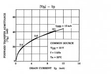
My experience varies, with respect to the graph from the 2SK170 DS, gm (dId/dVgs) is a very weak function of Idss. In fact the lines are not separable at 2mA operating current. I posted a fully differential current mirror loaded JC self biasing quad where trimming the mirrors independently gave 0.0 offset and 1ppm THD2 for badly (20%) matched FETs. THD3 is generally not affected much. A weak servo just to keep the offset 0 might be helpful to add.
Yes the trim process was a manual search "algorithm" the point being that at some ratio Id1/Id2,Id3/Id4 the offset and distortion both cancelled. Without help with isothermalness I don't think any technigue holds up perfectly.
Attachments
Hi Scott,
I remember your circuit very well")
It's just a pity that the general trend is to ignore such novel information and keep to old dogmas.
@AndrewT: it's a pity to see that now also you started to present your opinion as a fact, while you haven't even checked it. That's not proper engineering, but happens all the time here.
Well, what you do is that you merely assume that transconductance in the (arbitrary) range you specified is dominant in a distortion cancellation circuit. While that may be correct, it is completely unclear wether other mechanisms and manufacturing tolerances allow to see any advantages in real life.
I want just to remind you I have offered to measure a magic matched pair on an Audio Precision long time ago and nobody bothered to take the opportunity.
Maybe you can post some figures in the near future, I am of course interested.
Have fun, Hannes
I remember your circuit very well
It's just a pity that the general trend is to ignore such novel information and keep to old dogmas.
@AndrewT: it's a pity to see that now also you started to present your opinion as a fact, while you haven't even checked it. That's not proper engineering, but happens all the time here.
Well, what you do is that you merely assume that transconductance in the (arbitrary) range you specified is dominant in a distortion cancellation circuit. While that may be correct, it is completely unclear wether other mechanisms and manufacturing tolerances allow to see any advantages in real life.
I want just to remind you I have offered to measure a magic matched pair on an Audio Precision long time ago and nobody bothered to take the opportunity.
Maybe you can post some figures in the near future, I am of course interested.
Have fun, Hannes
Please remember this is meant to be a disscussion of technical issues not a confrontation. I have not tried it but a single diffpair would probably have the same properties (0 offset/0 THD2) if the trims were the current ratio and a small pot between the sources.
It would be nice to see how different techniques perform in large signal open loop circuits.
Single ended THD2 trimming is another set of problems, I see Salas has somone tweeking the simplistic RIAA. The perfect null does not yield to analysis easily.
It would be nice to see how different techniques perform in large signal open loop circuits.
Single ended THD2 trimming is another set of problems, I see Salas has somone tweeking the simplistic RIAA. The perfect null does not yield to analysis easily.
that is not the case,h_a said:@AndrewT: it's a pity to see that now also you started to present your opinion as a fact, while you haven't even checked it. That's not proper engineering, but happens all the time here.
in the context of matching and whether Vds matching is more appropriate than Idss matching.
I have stated that Idss selecting is almost worthless when looking for pairs that perform similarly at less than Idss current compared to Vds matching for near equal Id.
That has been done by test and measurement. It is not simply "an opinion"
I have never stated that distortion cancellation is due to the dominance of any particular parameter. That is your conclusion.h_a said:Well, what you do is that you merely assume that transconductance in the (arbitrary) range you specified is dominant in a distortion cancellation circuit. While that may be correct, it is completely unclear wether other mechanisms and manufacturing tolerances allow to see any advantages in real life.
I have stated that matching by one method does little to get the devices to perform on similar parts of the curve. I claim there are better ways to get the components to match. That is quite different from what you claim I have said.
Now let's extend this a little further.
Take two jfets with identical Idss (<0.05% tolerance)
set them up as an LTP and connect them to flow Idss through each by using zero for the gate resistor.
now apply a Vgs to the gate rather than using the shorted gate to source.
Increase the Vds until the Id equals Idss. You will find that with the gates connected and the sources connected that the Drains will flow identical currents and this will result in zero differential voltage between the drains.
Now reduce very slightly the the common Vgs applied to the jfets.
We have two alternatives.
Either the drain diff Voltage remains at zero.
or
the diff voltage becomes greater than zero.
In the first case we can imply thet the transconductance of the two devices match at Idss.
In the second case we can imply that the transconductance at Idss and for that tiny range just below Idss that the transconductance does not match.
Now take those two devices with unmatched transconductance and show me that they perform as identical amplifiers.
not a confrontation.
Of course, I apologize.
It's just a pity to see that even if there's solid information on a popular topic the general trend is to ignore it although everybody claims to be here to learn.
Well, we need myths I guess.
Have fun, Hannes
EDIT: Andrew, I didn't see your post before. I can only repeat myself, the magnitude of the effect is completely unclear and may be not seen in real life. That's why it has to be checked. I will let this topic rest as nothing usefull can emerge from this discussion. You are of course free to do whatever you like to improve your amps.
hitsware said:>It's not a resistor value, it's a current,
>that for IRF whatever needs to be too
>high for them to be temperature stable.
>That means, when they are temperature
>stable they are already too hot.
Then you can't use source resistors
the way you use emmitter
resistors with bi-polars ?
Sure, much smaller voltage drops on emitter resistors are needed to set emitter currents closer to each other than would be needed for MOSFETs. Millivolts of a negative feedback are needed to change base currents of paralleled transistors so this feedback would define their emitter currents, while Vgs variations are greater than such small voltage drops on similar resistors.
I think we are saying the same thing.scott wurcer said:with respect to the graph from the 2SK170 DS, gm (dId/dVgs) is a very weak function of Idss.
and when I apply it to BJTs I find the same.
hFE is a very weak function of Vbe.
I agree completely.h_a said:the magnitude of the effect is completely unclear and may be not seen in real life. That's why it has to be checked.
I am not competant to state nor measure what that magnitude is.
Similarly I cannot check whether it makes a big or small or any difference.
Do not try to put non existent words/claims into my posts.
AndrewT said:
Now take those two devices with unmatched transconductance and show me that they perform as identical amplifiers.
Andrew your matching method involving VDS is so alien to me that I would like to inquire as to what you consider "performing as an identical amplifier".
To be clear the school of detailed device matching and no trims or adjustments is a perfectly acceptible path. Certainly taking pots out of the direct signal path might be a goal to some. And the old trick of trimming and replacing the pot with R's can be as much work as the matching in the first place.
- Status
- Not open for further replies.
- Home
- Member Areas
- The Lounge
- John Curl's Blowtorch preamplifier part II