I’m just thinking loud here.
All of us know that in music there is nothing such a thing as a constant sine wave, both amplitude and frequency is changing. So why do we measure amps using constant values, fixed frequencies and amplitude?
What I’m thinking about is doing a multi tone test where the pitch of the sin waves is changing. (Just as an example a ½, ¼, 1/8 or 1/16 tone pitch change in let’s say 10 periods)
As an example we could use 20, 40, 80 200, 400, 800, 2k, 4k, 8k and 20k Hz.
Well it’s just an idea of how to measure the “musicality” of an amp.
Cheers.
john curl said:Sorry Jan, NOW my scanner won't come online.I could send them in the USA by FAX to someone who can post them.
I was out to visit relatives, found the circuit. It's now here:
http://www.linearaudio.nl/Miscellaneous/jc.JPG
Measurements are here:
http://www.linearaudio.nl/Miscellaneous/bias meas 2.jpeg
and here:
http://www.linearaudio.nl/Miscellaneous/meas ckt_.jpg
jd
stinius said:I’m just thinking loud here.
All of us know that in music there is nothing such a thing as a constant sine wave, both amplitude and frequency is changing. So why do we measure amps using constant values, fixed frequencies and amplitude?
What I’m thinking about is doing a multi tone test where the pitch of the sin waves is changing. (Just as an example a ½, ¼, 1/8 or 1/16 tone pitch change in let’s say 10 periods)
As an example we could use 20, 40, 80 200, 400, 800, 2k, 4k, 8k and 20k Hz.
Well it’s just an idea of how to measure the “musicality” of an amp.
Cheers.
Hint: Look up 'multitone testing'.
jd
janneman said:
Hint: Look up 'multitone testing'.
jd
Hint: read the post one more time.
S
janneman said:
I was out to visit relatives, found the circuit. It's now here:
http://www.linearaudio.nl/Miscellaneous/jc.JPG
Measurements are here:
http://www.linearaudio.nl/Miscellaneous/bias meas 2.jpeg
and here:
http://www.linearaudio.nl/Miscellaneous/meas ckt_.jpg
jd
Thanks John and Jan for putting these up.
The basic way in which the LT1166 is being used here is correct. The signal is not passing through the LT1166, but rather the LT1166 is being used as a shunt dynamic bias spreader.
There are a couple of questions on this information (these are not criticisms).
In the schematic, it does not appear that there is any feedback compensation. Is it supposed to be this way, or is the schematic incomplete in this regard. The way that feedback compensation is done when the LT1166 is used this way has a very big influence on the performance achieved.
In the performance plots, it looks like the LT1166 design is on the left and the conventional design with conventional bias spreader is on the right. Is this correct?
It looks like the top plots are THD spectra while the bottom ones are SMPTE IM residuals. Is that correct?
The notations seem to suggest that the magnitudes of the distortions are less witht the 1166, but with more high-order content. Is that correct? This pertains to interpreting the scale factors.
Thanks,
Bob
Bob Cordell said:
The basic way in which the LT1166 is being used here is correct. The signal is not passing through the LT1166, but rather the LT1166 is being used as a shunt dynamic bias spreader.
To start with, slap a 1uF (or more) film cap across pins 1 and 4 and everything will be one order of magnitude better. Depending on the measurement results, further refinements may or may not be required.
KSTR said:Doesn't that defeat the whole idea of the dynamic shunt regulator action? At least for higher frequencies?
Of course, but I wouldn't be concerned as long as a desired result is achieved. The bias is set by the source resistors and no further thermal compensation is required.
syn08 said:
To start with, slap a 1uF (or more) film cap across pins 1 and 4 and everything will be one order of magnitude better. Depending on the measurement results, further refinements may or may not be required.
This is not the way to go.
At frequencies where the capacitor dominates, the bias spreader formed by the LT1166 is no longer dynamic. A quasi-fixed bias spread obtained in this way is the wrong value, and will fluctuate with program material at a low frequency.
The functional objective of the LT1166 is to have the product of the currents of the top and bottom power transistors be a constant over the full audio range. This is accomplished by translinear circuitry in the LT1166. When this law is being obeyed, neither output transistor ever completely turns off. We thus have a non-switching output stage.
This can only happen by having the bias spread increase dynamically with the real-time magnitude of the current delivered to the load. Thus, when program material is present, the average value of the bias spread will increase. If this average is forced over a long period of time by a large capacitor, the output stage will be over-biased during program material.
Cheers,
Bob
Bob Cordell said:
This is not the way to go.
At frequencies where the capacitor dominates, the bias spreader formed by the LT1166 is no longer dynamic. A quasi-fixed bias spread obtained in this way is the wrong value, and will fluctuate with program material at a low frequency.
The functional objective of the LT1166 is to have the product of the currents of the top and bottom power transistors be a constant over the full audio range. This is accomplished by translinear circuitry in the LT1166. When this law is being obeyed, neither output transistor ever completely turns off. We thus have a non-switching output stage.
This can only happen by having the bias spread increase dynamically with the real-time magnitude of the current delivered to the load. Thus, when program material is present, the average value of the bias spread will increase. If this average is forced over a long period of time by a large capacitor, the output stage will be over-biased during program material.
Cheers,
Bob
Of course Bob, but this is still an excellent workaround to avoid some of the LT1166 HF issues. Without this cap, I have to agree with John and others that LT1166 will never achieve high performances. Of course the cap somehow defeats (at HF) the original purpose of the LT1166, but this is (according to my results) a very good trade off.
If you have a better way to avoid the LT1166 HF issues, please post a schematic and some results.
P.S. You could save some grey cells by avoiding lecturing me on the LT1166 functionality. Apparently, you haven't noticed my previous message and the link to the LT1166 internal schematic. Have you used that schematic to understand where the LT1166 issues are coming from?
P.P.S. I think the amp frequency compensation is totally irrelevant here. We are talking about minimizing the open loop HF distortions. If you mean the local LT1166 feedback compensation then I guess it's a schematic simplification. Without that compensation, the local feedback loop is totally unstable and those measurements couldn't be done.
scott wurcer said:It's pretty clear what stinius is proposing, it's a variant on multi-tone testing. One problem is sorting out the results using FFT techniques. Sliding tones might fill in everywhere and analog detection of the content in all the spaces might be prohibitive anyway.
The APx5xx software has what they (AP) call a continuous sliding sweep/chirp. Don't know the details but apparently they can do what Stinius proposes and still pick all results from the correct FFT bins. Been trying to find details to no avail.
jd
Hi Jan,
my guess would be they might use constant components on exact bin freq. per FFT block and adjust the multitone between blocks (and giving them some time to settle). Then they wouldn't need any windowing. But quite sure they AP guys came up with something more clever than this brute force (and slow) attack.
- Klaus
Inherent in the multi-tone test is the fact that both above and below IM components are present so the distortion products move at different speeds and in different directions. At some point one just makes interesting complicated pictures. I am assuming stinius was suggesting sliding all the tones at once. This would create a signal with a crest factor varying over time (more like music). Does AP do multiple sliding tones at once?
Some have suggested digitally taking real music and placing "holes" in the spectra. I have tried something similar in the analog domain at MHz frequencies with a noise diode and custom L/C filters. Works fairly well.
EDIT - I have a Linux library of totally arbitrary N and length FFT's. I have not used it in years but on a modern PC one could probably take an entire song and remove arbitrary bins in a couple of seconds compute time.
Bob Cordell said:
The functional objective of the LT1166 is to have the product of the currents of the top and bottom power transistors be a constant over the full audio range. This is accomplished by translinear circuitry in the LT1166. When this law is being obeyed, neither output transistor ever completely turns off. We thus have a non-switching output stage.
Bob, I (and others) have used geometric mean biasing. There are additional problems when extreme A/B biasing is present. The output stage can still switch off due to stored charge in the base (with bipolars).
LT1166; 1uF cap
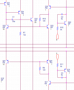
According to syn08's (reverse engineered) schematic there are a few a compensating caps (see pic below). However, preliminary sims suggest that these caps don't do their job very well.
BTW, there's another thing that isn't explained or fully covered by the data sheet: the product of the currents of the top and bottom power transistors is NOT held constant, rather it varies linear with the absolute temperature.
1uF cap across pins 1 and 4:
Hi Bob & Klaus,
Generally, I fully agree with that. However there might be one exception: If BJTs are used (having an exponential Ic/Vbe x-fer function) and if the value of Re is sufficiently low, then -at a constant bias voltage and temperature- the product of the currents of the top and bottom power transistors is already constant. So in this case a 1uF cap across the bias generator is not that detrimental.
edit: I'm not sure whether this also applies to syn08's amp.
Cheers,
Edmond.
Bob Cordell said:[snip]
In the schematic, it does not appear that there is any feedback compensation. Is it supposed to be this way, or is the schematic incomplete in this regard. The way that feedback compensation is done when the LT1166 is used this way has a very big influence on the performance achieved.
[snip]
Bob
According to syn08's (reverse engineered) schematic there are a few a compensating caps (see pic below). However, preliminary sims suggest that these caps don't do their job very well.
BTW, there's another thing that isn't explained or fully covered by the data sheet: the product of the currents of the top and bottom power transistors is NOT held constant, rather it varies linear with the absolute temperature.
1uF cap across pins 1 and 4:
KSTR said:Doesn't that defeat the whole idea of the dynamic shunt regulator action? At least for higher frequencies?
- Klaus
Bob Cordell said:This is not the way to go.
At frequencies where the capacitor dominates, the bias spreader formed by the LT1166 is no longer dynamic. A quasi-fixed bias spread obtained in this way is the wrong value, and will fluctuate with program material at a low frequency.
Hi Bob & Klaus,
Generally, I fully agree with that. However there might be one exception: If BJTs are used (having an exponential Ic/Vbe x-fer function) and if the value of Re is sufficiently low, then -at a constant bias voltage and temperature- the product of the currents of the top and bottom power transistors is already constant. So in this case a 1uF cap across the bias generator is not that detrimental.
edit: I'm not sure whether this also applies to syn08's amp.
Cheers,
Edmond.
Attachments
KSTR said:Hi Jan,
my guess would be they might use constant components on exact bin freq. per FFT block and adjust the multitone between blocks (and giving them some time to settle). Then they wouldn't need any windowing. But quite sure they AP guys came up with something more clever than this brute force (and slow) attack.
- Klaus
Klaus, Scott, yes. Although AP pioneered multitone testing without windowing by carefully synchronizing all frequency values and their phases, almost anybody seems to do it these days. As I said, I don't know how they do the chirp version, but it didn't look like a stepped approach.
BTW The need for carefull synchronizing etc gives you multitone components like 66.01Hz or 2,003Hz and such. Weird, but doable if your digital generator has enough bits.
jd
- Status
- Not open for further replies.
- Home
- Member Areas
- The Lounge
- John Curl's Blowtorch preamplifier part II