An important note (I already guessed that), thanks!Justcallmedad said:First schematics, those posted by flg where only intended for learning, trying and illustration purposes…
The more detailed one show buffered followers to unload the refs? BTW, why the JFET drain resistors. practical issues?
- Klaus
KSTR said:An important note (I already guessed that), thanks!
The more detailed one show buffered followers to unload the refs? BTW, why the JFET drain resistors. practical issues?
- Klaus
Not to unload refs but to dont load the RC filter by a bjt, and to get a low impedance for the shunt bjt . Drain resistances are used to reduce the voltage across the fet (Low Vds)
Justcallmedad said:First schematics, those posted by flg where only intended for learning, trying and illustration purposes…
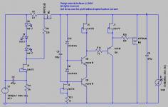
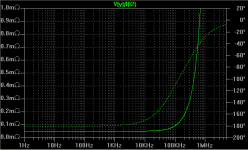
Last ones in post 93 are fully functional Zout is about 0.5R from 0 to a few tenth of Mhz(I cant measure beyond) noise is -150 db from 100hz to 100 kHz (can't measure beyond neither ) and decreasing to -130 db at 10Hz of course there is no feedback "loop", for me the shunt bjt is 100% “feedback”.
New PSU
Really, that last shunt regulator can't be considered "local feedback", but full blown global NFB. The error amp is now the JFET and the open loop gain of this "opamp" is about Beta*(Gm-jfet/Gm-bipolar). Hence, the output impedance (essentially 1/Gm-bipolar) is divided by the loop gain and is at the end of the day about 1/(Beta*Gm-jfet). The bipolat shunt regulator acts as a Gm-jfet multiplier (by Beta).
I agree this discrete regulator has very good frequency response, but still the LF output impedance is nothing to call home about. I am surprised by the noise performance you measured. Anyway, a wideband, low noise opamp like THS4031 in the same configuration and a bandgap reference instead of the LED will do a much better job.
bear said:
So I am thinking why not a choke or a pi filter in the same spot?
_-_-bear
An air core inductor works rather well in this application.
I made some 5mH ~10DCR coils for heading a shunt reg a while back, as I found it to be the simple, proven solution.
A series reg in place of the inductor was also tested, but the inductor offered at least the same performance, caused less heat, and took up less space.
My scope is not exactly of the newest generation, so in this end of the scale, I can't provide reliable measurements.
Magura
")
KSTR said:Syn08, I don't see any other "error amp" than that single Vbe junction. The JFET just buffers the refs to a lower source impedance, driving the base... but that might be semantical issues...
- Klaus
It might be semantical
The inverting input is the gate, the non inverting input is the source and the output is the drain. The output is loaded by the resistor and the bipolar rb'e, that is about Rload=rb'e. The non-inverting input at the ground is nothing else but "unity loop gain".The voltage gain of the "opamp" is then Vo/Vi=Gm-jfet*Rload=Gm-jfet*(Beta/Gm-bipolar)
But then again (we are refering to this, neg side, are we?) the JFET drain is not involved in the circuit at all as could be hooked to any potential to make the FET work with no change in circuit behavior (EDIT: and same thing for the collector, except for the return current path we want in the first place)? But we can leave it at that, it's not worth any hair-splitting IMHO.
syn08 said:It might be semantical
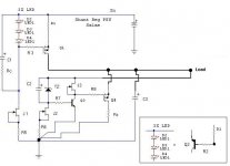
Like in this one. But the jfet is the load in this case. Has a cascode and a buffer, and it does not oscillate, its a working example.
Attachments
KSTR said:But then again (we are refering to this, neg side, are we?) the JFET drain is not involved in the circuit at all as could be hooked to any potential to make the FET work with no change in circuit behavior (EDIT: and same thing for the collector, except for the return current path we want in the first place)? But we can leave it at that, it's not worth any hair-splitting IMHO.
Yes; I assumed there are "dots" along the ground wire.
I agree, this is somehow hair splitting. To me, even the notion of "regulator" assumes somehow there's something to return the error information and doing some corrective action to minimize the error, therefore feedback.
KSTR said:Salas,
your one qualifies as global NFB IMHO, as we now have a "real" error amp: (cascoded) VAS plus bjt-buffered source follower.
- klaus
Yes indeed. I have shown it after syn08's loop explanations rang a bell.
KSTR said:No, check the polarities of the MOSFETs and the way they are hooked up (ignoring the source resistors for a moment). Best seen on the neg side, the source follows the drop on that R to gnd, impessed by the JFET ccs.
- Klaus
Ahh I see, constant Vgd instead of Vgs. Hmmm.
Jan Didden
KSTR said:
EDIT: BTW, only one Vbe accross J5+R21?
- klaus
Yes just because J5 is a very low pinch off part. Vbe can be lifted higher with a resistor under the lower cascode bjt to ground if needed. It works as it is with 2SK170. (We had many of them left out from matching in an open loop Riaa stage
).Salas said:
Yes just because J5 is a very low pinch off part. Vbe can be lifted higher with a resistor under the lower cascode bjt to ground if needed. It works as it is with 2SK170. (We had many of them left out from matching in an open loop Riaa stage
You are learning fast
N channel JFETs have negative pinch voltages; depending on transconductance as well, they can reach incipient saturation at very low Vds. The rule of thumb is: two pinch voltages away from the (negative) pinch voltage is good enough. That is, for 2SK170 parts, Vt=-0.5V => Vds=0.5V is already good enough.- Status
- Not open for further replies.
- Home
- Member Areas
- The Lounge
- John Curl's Blowtorch preamplifier part II