"Scott:
If AD won't repair a scope where do they go? Might there be deals we should know about? "
I was very, very lucky about 4 months ago. I picked up a 200MHz analog scope - for zip. The guys in our lab did not like it because instead of rotary knobs, it uses push buttons and a user I/F feedback via the display. It sat in the lab for about 8 years and was hardly used. The old 10MHz Hitachi I had was duly retired to the skip just before I left Japan.
")
If AD won't repair a scope where do they go? Might there be deals we should know about? "
I was very, very lucky about 4 months ago. I picked up a 200MHz analog scope - for zip. The guys in our lab did not like it because instead of rotary knobs, it uses push buttons and a user I/F feedback via the display. It sat in the lab for about 8 years and was hardly used. The old 10MHz Hitachi I had was duly retired to the skip just before I left Japan.
Looking at PMA's picture from a few pages back, I see transitions taking place during each of the ladder steps. This is exactly what you would expect to see if you applied 1LSB of dither. If this is applied in the context of a subtractive dither scheme (i.e. with the associated digital filter), I fail to see how this is 'fuzzy distortion'. We added the dither, we converted it (a stream of 1's an 0's with a mathematically predictable pattern), and we then filtered it out. No doubt, multibit converters look easier to apply on the face of it, and, you don't have as much of that filter math to worry about. But, surely that does not automatically quality them as superior? Like jcx and a whole lot of other people here have said before: you cannot look at PMA's picture (or similar) and compare it to a multibit converter and claim the latter has 'fuzzy distortion - you have to consider the [converter+filter]. Secondly, the points made earlier on about bandwidth - no point in having wideband multibit DAC's for conventional CD when the material is already bandwidth limited in the recording process. Measurements don't lie. ;-)
Last edited:
Hi,
I am not sure that this is really true.
There are currently no measurements in in wide use that where not documented and possible 40 Years ago or longer (for example - impulse response measurements on speakers go back at least to the mid/late 1930's in Germany with at least Eckmiller but likely others).
What has changed is that nowadays equipment is widely available and relatively affordable to procure to carry out all these measurements repeatable and easily, compared to 40 years ago, when many such measurements required highly specialised, very expensive instrumentation in extremely limited supply.
In fact, a 192KHz Pro-Sound external soundcard like the EMU1616m and a decent microphone plus some software allows pretty much all these measurements to be taken for Speakers, Electronics and the system is even sensitive enough to illustrate some of the grosser effects in cables.
This indeed is very true. However, the "orthodox" audio community has vigerously resisted the introduction of any adjustments to the established set of measurements.
An example of such are the many attempts since the days of Harry Olson of the RCA, "Cathode Ray" M.G. Scroogie, D.E.L. Shorter of the BBC and most recently Geddes/Lee to replace THD with a distortion metric that takes distortion audibility into account and running for over 50 Years at least.
Still THD & N remains.
There is nothing wrong with this approach. It is in fact one I employ as standard.
But forgive me for asking, what is wrong with presenting an alternative viewpoint and interpretation, derived from this method, that makes it imperative to try all possible and with all possible might (all the way to getting quite insulting) to discredit such viewpoints and those presenting them and to talk the points raised away and to hope the people presenting them will eventually get the hint and just go away?
Ciao T
Well put, but don't forget that audio engineers have learned a thing or two about measuring sound performance in those 40 years.
I am not sure that this is really true.
There are currently no measurements in in wide use that where not documented and possible 40 Years ago or longer (for example - impulse response measurements on speakers go back at least to the mid/late 1930's in Germany with at least Eckmiller but likely others).
What has changed is that nowadays equipment is widely available and relatively affordable to procure to carry out all these measurements repeatable and easily, compared to 40 years ago, when many such measurements required highly specialised, very expensive instrumentation in extremely limited supply.
In fact, a 192KHz Pro-Sound external soundcard like the EMU1616m and a decent microphone plus some software allows pretty much all these measurements to be taken for Speakers, Electronics and the system is even sensitive enough to illustrate some of the grosser effects in cables.
It seems to me that understanding measurement processes as well as the particular numerical results can help narrow down the interpretation of the results.
This indeed is very true. However, the "orthodox" audio community has vigerously resisted the introduction of any adjustments to the established set of measurements.
An example of such are the many attempts since the days of Harry Olson of the RCA, "Cathode Ray" M.G. Scroogie, D.E.L. Shorter of the BBC and most recently Geddes/Lee to replace THD with a distortion metric that takes distortion audibility into account and running for over 50 Years at least.
Still THD & N remains.
Rather than say we should only test with objective equipment or only test with subjective listeners, what's wrong with testing with both techniques?
There is nothing wrong with this approach. It is in fact one I employ as standard.
But forgive me for asking, what is wrong with presenting an alternative viewpoint and interpretation, derived from this method, that makes it imperative to try all possible and with all possible might (all the way to getting quite insulting) to discredit such viewpoints and those presenting them and to talk the points raised away and to hope the people presenting them will eventually get the hint and just go away?
Ciao T
Of course, you should use measurements, especially for design. I have a whole roomful of test equipment. I wouldn't mind an even better equipped lab with free technicians as well, but considering that it's all mine, it's OK.
Thorsten is right, the actual measurements have not changed much from even 60 years ago. We have replaced wave analyzers with FFT driven analyzers, and made it cheaper for the general public to have access of serious measurements by using their home computer, but it really has not changed much. That is the problem.
Over 40 years ago, Richard Heyser told me that the trouble with test equipment is that it is composed of circuitry that we would not happily make quality audio products, for the most part, so that the test procedure must be missing some essential aspect of measurement because it is ignored by the process that we measure with.
For example, SMPTE IM, once the 'gold standard' for audio testing is completely blind to TIM, so we found many circuits that could measure as low as 0.001% IM distortion would actually sound pretty bad in practice. This is because only a small part of the distortion spectrum is actually detected, by the test standard itself.
Today, 2 or 3 tone IM with an FFT based analyzer can do much better, it is still only a limited sort of signal, compared to real music. This seems to be the problem, and why we have to listen as well to be sure.
Hi,
I found the reference to Harry F. Olson's work on "weighted distortion" that I was looking for.
Olson, H.F. "Elements of acoustic engineering" (D. Van Nostrand Co. Inc., New York, 2nd Edition 1947)
I was quite shocked to realise that the documented criticism and te offers of a better alternative go as far back as that.
It does both beggar believe and strongly argues against much, if any, progress having been made in Audio Measurements since then...
Ciao T
An example of such are the many attempts since the days of Harry Olson of the RCA, "Cathode Ray" M.G. Scroogie, D.E.L. Shorter of the BBC and most recently Geddes/Lee to replace THD with a distortion metric that takes distortion audibility into account and running for over 50 Years at least.
I found the reference to Harry F. Olson's work on "weighted distortion" that I was looking for.
Olson, H.F. "Elements of acoustic engineering" (D. Van Nostrand Co. Inc., New York, 2nd Edition 1947)
I was quite shocked to realise that the documented criticism and te offers of a better alternative go as far back as that.
It does both beggar believe and strongly argues against much, if any, progress having been made in Audio Measurements since then...
Ciao T
Looking at PMA's picture from a few pages back, I see transitions taking place during each of the ladder steps. This is exactly what you would expect to see if you applied 1LSB of dither. If this is applied in the context of a subtractive dither scheme (i.e. with the associated digital filter), I fail to see how this is 'fuzzy distortion'. We added the dither, we converted it (a stream of 1's an 0's with a mathematically predictable pattern), and we then filtered it out. No doubt, multibit converters look easier to apply on the face of it, and, you don't have as much of that filter math to worry about. But, surely that does not automatically quality them as superior? Like jcx and a whole lot of other people here have said before: you cannot look at PMA's picture (or similar) and compare it to a multibit converter and claim the latter has 'fuzzy distortion - you have to consider the [converter+filter]. Secondly, the points made earlier on about bandwidth - no point in having wideband multibit DAC's for conventional CD when the material is already bandwidth limited in the recording process. Measurements don't lie. ;-)
Of course with a 24 bit audio converter you are not going to resolve 24 bit LSB steps nor are you going to see 10 bits of noise.
John,
I should think so.
My recommendation would be to employ a sawtooth signal at around -60dBFS (below that you need active probes with gain with most 'scopes) with a frequency is a integer quotient of the sample rate with a reasonably high frequency , so maybe Fs/8 or Fs/16.
This way you can ignore any interference effects from "cycle slips" in the digital sampling.
Setting the scope to infinite persistence (if it is a digital storage scope) will show the resulting error band, if there are random errors they will lead to a widening of the signal lines displayed, the degree of widening allows an estimation of the degree of "fuzzy distortion" or noise present.
Using single shot will show the waveform. Ideally here one overlays the two traces and uses dual channels, one DS DAC the other MB.
Some here have made the point that things should be viewed only after the analogue post filter. THis is true to a degree, HOWEVER it is also quite instructive to look directly at the output of the DAC as post filtering can only attenuate any given artefacts, but not remove them.
Ciao T
Thanks a real experiment to try. Didn't you say last week a multi-bit converter was really 10bits and all the rest dither (there are too many post to go back and search over). If that was the case, how could -60dB (~10bits) be even resolvable? There should be nothing but noise with the signal recovered by averaging (filtering?).
Hi,
This experiment was implicit in earlier comments.
I do not remember saying anything of the like.
I said that low bit converters had a very limited "direct" resolution, amounting usually to less than 10Bit . One may also say that such a converter can only resolve a very limited number of levels for any individual sample and intermediate values can only be attained by averaging multiple samples.
Yup, however most modern low bit DAC's include switched capacitor filters and other means of "hiding" reality.
The old Nippon Precision Circuits SM5872 DS DAC used widely in the Marantz CD63/67/6000 Series CD-Players was completely unfiltered and showed things up magnificently.
Ciao T
Thanks a real experiment to try.
This experiment was implicit in earlier comments.
Didn't you say last week a multi-bit converter was really 10bits and all the rest dither
I do not remember saying anything of the like.
I said that low bit converters had a very limited "direct" resolution, amounting usually to less than 10Bit . One may also say that such a converter can only resolve a very limited number of levels for any individual sample and intermediate values can only be attained by averaging multiple samples.
If that was the case, how could -60dB (~10bits) be even resolvable? There should be nothing but noise with the signal recovered by averaging (filtering?).
Yup, however most modern low bit DAC's include switched capacitor filters and other means of "hiding" reality.
The old Nippon Precision Circuits SM5872 DS DAC used widely in the Marantz CD63/67/6000 Series CD-Players was completely unfiltered and showed things up magnificently.
Ciao T
S-D A/D conversion
Okay, I tried something myself.
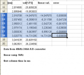
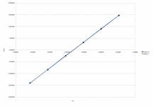
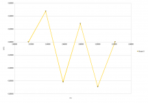
48kHz/24bit A/D converter is excitated by linear ramp (1kHz triangle), created by 24bit D/A converter. A/D samples are stored in memory (no averaging, one-shot measurement) and shown in the table 'graf0'. Linear and settled portion of the triangle is shown. Then we can see amplitude values after A/D, expressed in %FS. The 3rd plot is the error of captured data vs. linear approximation - from endpoints of the plot.
P.S. Amplitude of the 1kHz triangle is from -67%FS to +67%FS. The portion in plots is from -14%FS to +15%FS.
Okay, I tried something myself.
48kHz/24bit A/D converter is excitated by linear ramp (1kHz triangle), created by 24bit D/A converter. A/D samples are stored in memory (no averaging, one-shot measurement) and shown in the table 'graf0'. Linear and settled portion of the triangle is shown. Then we can see amplitude values after A/D, expressed in %FS. The 3rd plot is the error of captured data vs. linear approximation - from endpoints of the plot.
P.S. Amplitude of the 1kHz triangle is from -67%FS to +67%FS. The portion in plots is from -14%FS to +15%FS.
Attachments
Last edited:
Uncorrelated noise sums to 3dB. Signal and correlated noise sum to 6dB. That's a 3dB gain (re uncorrelated noise) if the outputs of the two ADCs are summed. I don't see the issue.
edit: Same argument for "differenced" as well.
I missed this conversation (or ignored it). Thorsten are you saying that if I take two 2SK170's running at 1mA (~1nV) and parallel them at 2mA total the RTI noise is 1.4nV rather than .7nV? Of course if you make a diff amp you have half the gain so then the combination of corellated input vs uncorellated noise gives 3dB degradation of SNR. This is the Blowtorch thread after all and you question its very claim to fame?
The same argument applied to paralleling resistors violates the first law directly.
Yup, however most modern low bit DAC's include switched capacitor filters and other means of "hiding" reality.
The old Nippon Precision Circuits SM5872 DS DAC used widely in the Marantz CD63/67/6000 Series CD-Players was completely unfiltered and showed things up magnificently.
Ciao T
Hiding reality or finishing the job right? If you need to find crap implementations to "prove" that the audio industry is pulling the wool over everyones eyes what's the point. Why not capture a test signal on a decent quality prosumer 24bit field recorder with modern A/D's in a decent implementation.
The built-in soundcard in a cheap laptop probably looks as you say.
EDIT - For goodness sake that NPC product puts out a pwm signal not an analog out.
Last edited:
Pavel,
So you have an eleven bit system. It must be due to micro diodes in the connecting cables!
Scott,
Do you really misunderstand the paralleled amplifier S/N improvement issue? It is an old technique dating back to the early sonar work. Uncorrelated noise adds by 3 db, correlated signal by 6 so every time you double the paralleled amplifier channels you get a 3 db improvement in signal to noise.
Scott,
Matter of debate, arguably and what we have been debating.
I would not call the implementation "excremental", it is actually quite good, within the limits it is subject to. Many Marantz CD-Players highly regarded in terms of sound quality for money in their time used this DAC.
I am pointing to it simply because it makes the problems dramatically visible. After you seen them there is becomes much easier to spot them at lower levels elsewhere.
Why not indeed. I do happen to have a nice analog function generator in the lab and as it so happens one of the best prosumer recording/playback devices available (on measured performance anyway, which is what I use it for).
So I may do exactly that...
Yes, so it must be filtered. Even after a lot of poles as implemented by Marantz there remains a surprising amount of rubbish, though less than any SACD player I have measured...
Ciao T
Hiding reality or finishing the job right?
Matter of debate, arguably and what we have been debating.
If you need to find crap implementations to "prove" that the audio industry is pulling the wool over everyones eyes what's the point.
I would not call the implementation "excremental", it is actually quite good, within the limits it is subject to. Many Marantz CD-Players highly regarded in terms of sound quality for money in their time used this DAC.
I am pointing to it simply because it makes the problems dramatically visible. After you seen them there is becomes much easier to spot them at lower levels elsewhere.
Why not capture a test signal on a decent quality prosumer 24bit field recorder with modern A/D's in a decent implementation.
Why not indeed. I do happen to have a nice analog function generator in the lab and as it so happens one of the best prosumer recording/playback devices available (on measured performance anyway, which is what I use it for).
So I may do exactly that...
EDIT - For goodness sake that NPC product puts out a pwm signal not an analogue out.
Yes, so it must be filtered. Even after a lot of poles as implemented by Marantz there remains a surprising amount of rubbish, though less than any SACD player I have measured...
Ciao T
Ed,
in 1995 Burr-Brown catalogue, you will find:
ADC614 - 14-bit, 5.12MHz sample rate A/D converter
ADC701/SHC702 - 16-bit, 512kHz sampling A/D converter system
ADS610 - 14-bit 10MHz sampling A/D converter
ADS703 - 16-bit 2.5MHz sampling A/D converter
ADS704 - 18-bit 500kHz sampling A/D converter with 96dB SNR!!
DAC707 - 16-bit 8us settling D/A converter
None of them is sigma-delta.
Pavel,
So you have an eleven bit system. It must be due to micro diodes in the connecting cables!
Scott,
Do you really misunderstand the paralleled amplifier S/N improvement issue? It is an old technique dating back to the early sonar work. Uncorrelated noise adds by 3 db, correlated signal by 6 so every time you double the paralleled amplifier channels you get a 3 db improvement in signal to noise.
ED - How can you so mis-read what I said. (page 1)http://www.analog.com/static/imported-files/application_notes/5866763300941AN245.pdf
I saw this...
>You started by claiming that two analog signals in parallel (balanced) reduces S/R by 3 dB.<
...and pointed out that the same two input devices can be paralleled or used balanced and then you see the +3dB vs -3dB SNR issue. I was praying that might have been the confusion in that conversation.
Or maybe the confusion was the use of reduce as in making worse vs. making a negative number smaller. I usually use SNR as a positive number.
EDIT - I'm from the colonies it's analog here not analogue
Last edited:
ED - How can you so mis-read what I said. (page 1)http://www.analog.com/static/imported-files/application_notes/5866763300941AN245.pdf
I saw this...
>You started by claiming that two analog signals in parallel (balanced) reduces S/R by 3 dB.<
...and pointed out that the same two input devices can be paralleled or used balanced and then you see the +3dB vs -3dB SNR issue. I was praying that might have been the confusion in that conversation.
Or maybe the confusion was the use of reduce as in making worse vs. making a negative number smaller. I usually use SNR as a positive number.
EDIT - I'm from the colonies it's analog here not analogue
Scott,
Even when we agree we disagree! Analogue is an e-zine, Analog is on paper since the 30's.
How can I believe your '83 EDN article when it is PDF'd crooked?
The problem still is micro diodes!
ES
Any comment on my noise analyzer project?
(My first Fourier Analyzer was built around the Reticon analog shift register chip! So the SAD-1024 was a nice flashback.)
Last edited:
Ed,
in 1995 Burr-Brown catalogue, you will find:
ADC614 - 14-bit, 5.12MHz sample rate A/D converter
ADC701/SHC702 - 16-bit, 512kHz sampling A/D converter system
ADS704 - 18-bit 500kHz sampling A/D converter with 96dB SNR!!
...
None of them is sigma-delta.
Pavel,
We are not arguing. When I look at devices I can find real 16 bits! Some I have not tried claim 20.
I see some listed with a "resolution" of 24 bits, but the other data leads to no more than 20 bits. Maybe SY should have a chat with them.
ES
Any comment on my noise analyzer project?
You'll have to refresh my memory, multi-tasking has reached a limit.
Scott,
Replay!
With that in mind I am starting to build a noise analyzer. I am aiming for .1 to 1,000,000 hz. range. I expect actually to only break that into octaves and use a peak detector. I might also consider some sort of slow decay detector. Due to the limited bandwidth I do not expect to consider RMS. The DC level would go to a log converter then into a multiplexer. The output would be a digital scope display.
I can use Biquad filters for all but the highest range. The version that starts with the LPF stage also adding gain is the preferred approach. I suspect I need to play with a biquad or LC for the top octave. I may need to use a discrete front end for the low frequency stages.
I haven't yet come up with a good decision on the input impedance. I expect to be able to get within 3 db of the noise floor.
On another thread there is a fellow who seemed to improperly identify an IC. So for fun I thought I would list partial part numbers and see who can correctly identify the part. For example 741 would be a uA741 the first commercial op amp with built in compensation introduced by Fairchild.
47 (More than one answer!), 072, 83, 107, 300, 555, 703, 709, 722, 923, 7400
Any takers?
ES
- Status
- Not open for further replies.
- Home
- Member Areas
- The Lounge
- John Curl's Blowtorch preamplifier part II