But could you get the same distortion levels with only 20 dB of feedback around the ENTIRE LOOP, by reducing the Gm of the input stage further, perhaps, rather than putting the extra gain back into the input from the driver stage? Or would a passive pair of resistors to ground be a better method to get 20dB of feedback, overall. Please remember, I am paralleling Lohstroh-Otala, in this design example.
"assuming your conclusions" is a circular argument - not the same as analyzing what the circuit does
if you are now talking about
JAN LOHSTROH and MATT1 OTALA, "An Audio Power Amplifier for Ultimate Quality Requirements"
IEEE TRANSACTIONS ON AUDIO AND ELECTROACOUSTICS, VOL. AU-2 1, NO. 6, DECEMBER 1973
for this discussion sufficient criticism is that the Lohstroh Otala circuit introduces a extra gain stage (and don't you consider diff pair “VAS” with current mirror more complicated than just 1 stage?) heavily degenerates each, and adds a little local pole cancellation that actually makes it much more "conventional" in terms of degeneration/local feedback at high frequency
I think the text is less than illuminating - probably the "loaded" language referencing the AES debate was missed by the IEEE reviewers
but I don't see how you come to the conclusion from that paper than the JC-3 "inner loop" feedback R are working in their formalism
as I keep stating, the analysis result of how the JC-3 inner feedback R "works" is completely independent of why you thought it was a good idea at the time
when you state that the local feedback reduces the internal driver node Z and that reduces distortion in the closed loop amplifier from Ierror at the inner node you are making a circuit operation claim testable with Bode sensitivity analysis - that is what my simplified sim is about
by the way university EE programs have been teaching feedback circuit analysis for 50+ years the "reduced Z from inner feedback reduces distortion from Ierror at that node" is simply not true for the JC-3 topology - the sensitivity is for all practical purposes is the SAME with or without the inner feedback R in the JC-3 topology to beyond audio frequencies
Attachments
Last edited:
Another simple experiment
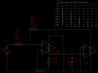
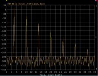
Here's a cute demo of "re-entrant" distortion or whatever you want to call it. Take just about the simplest representation of an "op-amp" , a gm (5mS), R, (2Meg so Aol = 10k), and a C (100pf), ideal output stage, and put feedback around it. Give the C a voltage coefficient (C = 100pf + 1pF*V*V). With only the square law variation of C all odd harmonics are generated in a decending amplitute with frequency. Here I have about 16V p-p at 5kHz. I'll say nothing about adding local feedback, anyone can do the experiment (Hint: you don't need another plot.)
Here's a cute demo of "re-entrant" distortion or whatever you want to call it. Take just about the simplest representation of an "op-amp" , a gm (5mS), R, (2Meg so Aol = 10k), and a C (100pf), ideal output stage, and put feedback around it. Give the C a voltage coefficient (C = 100pf + 1pF*V*V). With only the square law variation of C all odd harmonics are generated in a decending amplitute with frequency. Here I have about 16V p-p at 5kHz. I'll say nothing about adding local feedback, anyone can do the experiment (Hint: you don't need another plot.)
Attachments
Last edited:
So, JCX, what are you trying to prove? That adding two extra resistors was a waste of time or worse? OK. But that is not why I added them at the time. I added the resistors to eliminate the need to put a pair of similar, but lower value resistors to ground, to achieve the same INTENT, i.e. to have only 20dB of negative feedback in the total overall feedback loop. This is how it is commonly done, and I thought to do it one better.
Now, can adding a resistor (or 2) at that point 'improve' an amp, or an IC, if you have access to the high impedance node driving the output stage?
Well, I had some success with that with the HA911, our best IC at the time, for audio work. It had a frequency compensation pin that could be accessed. By putting a resistor there of the proper value (1 meg ohm) to ground, 40 dB of open loop gain would be lost, the open loop bandwidth would extend to 10KHz, (rather than 100Hz) AND the measured IM distortion would DROP in the examples I tried. How could this be?
I can only attribute it to linearizing the driver, by swamping the relatively high impedance developed by two transistor collectors, and/or providing a relatively low drive impedance to the output followers that forced less influence of beta nonlinearity, easily and obviously seen in open loop measurements of the device, unless selected.
In any case, I tried it with the HA-911 and it worked well, so I gave it a shot with the JC-3.
"we are not amused" - that audio gurus writing articles on feedback don't follow this
the intent to "reduce loop gain to 20 dB" is not illuminating how the inner feedback resistors actually change the JC-3 circuit's closed loop performance with respect to
"linearizing the driver, by swamping the relatively high impedance developed by two transistor collectors, and/or providing a relatively low drive impedance to the output followers that forced less influence of beta nonlinearity, easily and obviously seen in open loop measurements of the device,.."
perhaps you are stuck on the "1st step" - the inner feedback R does reduce the high impedance node Z when measured with the global loop opened
apparently you stop the analysis here
I ask "the next question" - how does the inner feedback R affect the (globally) closed loop response of the amplifier to the same influences?
the answer is that when you close the loop the "influences" represented by injecting a Ierror into the node show the same sensitivity without the inner feedback R
a way to think about it is that the inner local feedback reduced the error by very closely the same amount it reduced the open (global) loop gain
so you end up in the Red Queen's race, "spending" loop gain to reduce the inner node Z, costing "the same" amount off the global loop gain, reducing global loop effectiveness to very nearly exactly compensate – back where you (would have) started without the inner loop feedback
If you add gain stages, local feedbacks then you may see “improvements“, not in this simple topology where you haven’t added gain, just “rearranged” it
My simple version Bode sensitivity analysis sim can show the inner loop Z reduction, and that it doesn’t change the response when the global loop is closed
http://www.diyaudio.com/forums/anal...ch-preamplifier-part-ii-1581.html#post2705814
I expected people working at the pro EE level of circuit design would be able to do the Bode sensitivity sims, plots, particularly with eveything set up for them
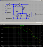
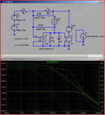
below shows the inner loop Z reduction of node X impedance with the global loop open
then the response to the same Ierror at node x with the global loop closed
and the 3rd is a "simple Middelbrook" loop global loop gain test
yellow is with John's inner loop feedback R, green without - but outer loop gain compensated by Rcorr
a further step would be to insert the loopgain probe "inside" the inner feedback and see how (not) much the "total" loop gain changes with the inner feedback R
the intent to "reduce loop gain to 20 dB" is not illuminating how the inner feedback resistors actually change the JC-3 circuit's closed loop performance with respect to
"linearizing the driver, by swamping the relatively high impedance developed by two transistor collectors, and/or providing a relatively low drive impedance to the output followers that forced less influence of beta nonlinearity, easily and obviously seen in open loop measurements of the device,.."
perhaps you are stuck on the "1st step" - the inner feedback R does reduce the high impedance node Z when measured with the global loop opened
apparently you stop the analysis here
I ask "the next question" - how does the inner feedback R affect the (globally) closed loop response of the amplifier to the same influences?
the answer is that when you close the loop the "influences" represented by injecting a Ierror into the node show the same sensitivity without the inner feedback R
a way to think about it is that the inner local feedback reduced the error by very closely the same amount it reduced the open (global) loop gain
so you end up in the Red Queen's race, "spending" loop gain to reduce the inner node Z, costing "the same" amount off the global loop gain, reducing global loop effectiveness to very nearly exactly compensate – back where you (would have) started without the inner loop feedback
If you add gain stages, local feedbacks then you may see “improvements“, not in this simple topology where you haven’t added gain, just “rearranged” it
My simple version Bode sensitivity analysis sim can show the inner loop Z reduction, and that it doesn’t change the response when the global loop is closed
http://www.diyaudio.com/forums/anal...ch-preamplifier-part-ii-1581.html#post2705814
I expected people working at the pro EE level of circuit design would be able to do the Bode sensitivity sims, plots, particularly with eveything set up for them
below shows the inner loop Z reduction of node X impedance with the global loop open
then the response to the same Ierror at node x with the global loop closed
and the 3rd is a "simple Middelbrook" loop global loop gain test
yellow is with John's inner loop feedback R, green without - but outer loop gain compensated by Rcorr
a further step would be to insert the loopgain probe "inside" the inner feedback and see how (not) much the "total" loop gain changes with the inner feedback R
Attachments
Last edited:
That is cute. Can you show us one with a 2nd harmonic?

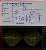
Sure, just make C have a straight linear with V relationship. 100pf + 10pF*V is strong but shows the point. Odds and evens show up, you can imagine a full polynomial expansion of C (~V^.33) would look "interesting". Distortion caused by nothing but feedback, what a concept (not new).
This example is so simple you could write out the node equations and solve for the polynomial solution directly. The simulator does the same thing iteratively.
Attachments
Last edited:
AND the measured IM distortion would DROP in the examples I tried. How could this be?
You could have moved the phase of some of the distortion components to change the sum. Every year or so a technician comes to me and asks why a distortion vs frequency plot has a suckout that looks like a twin-tee filter hit it.
Dear Scott,
Now I have been reliably informed by my people that they finally located a kind of matter that is more dense than the stuff beyond the event horizon of a singularity. Apparently I am carrying it around inside my skull. I never knew!
Anyway, back on topic, please explain to me why exactly I would want to use such a capacitor in my amplifier? Now I understand the capacitors inside IC's are very bad, I hope sincerely where they matter they are better that that if used as dominant pole.
I have this nasty habit of making my own cap's for this dominant pole job from PTFE Coax Cable (which incidentally also allows them to be easily adjusted for optimising transient response), if this becomes impractical, I use silver mica, which I happily enough can get made up to several 100nF if I order enough.
Now I understand the didactic purpose of this particular strawman (I hope you understand the same purpose in my own ones), but honestly, you are loosing most of the audience and you are boring me to death. I think I just lost pulse for several seconds.
Please show something REAL.
Either a Sim that is sufficiently REAL (it gets really complex to that but with sufficient time and willpower it is possible), or a real circuit.
I have spend a long time learning that in theory there is no difference between theory and practice, while in practice there is very poor congruence between practice and theory.
To be clear, the underlying topic of debate, just to distil it, this is:
Is it is better for suppressing higher order harmonics, reducing bandwidth modulation that leads to PIM, reducing distortion multiplication etc/et al (in other words all these very real issues normal op-amp theory likes to sweep to the nearest rug but which by extensive anecdotal evidence appear to have a connection to "bad sound") to:
A) Concentrate all available gain in the main outer loop, eliminating all degeneration etc.?
B) Find a correct balance between using degeneration for individual stages, local loops where needed and an outer loop?
C) Abandon the outer loop entirely and use only local loops and degeneration?
D) Abandon any looped feedback and rely only on degeneration?
Note that lowest THD does not provide the above requirements, nor lowest IMD. I will personally nail my flag to the mast of D.E.L. Shorters suggested weighting for harmonics/IMD, but I also accept Gedlee Metrics, we may even (reluctantly) agree on Olson's weighting.
Well, here is distilled the challenge. Real circuits with real performance please.
Ciao T
PS, of course I expect this post will be seen as "too confrontational" by some, probably the same people who have no issue with "challenging" anyone claiming to hear differences from disputed issues to a DB Test. What is good for the goose and all I guess.
PPS, I also expect that they will run crying to the moderators to stop such disrespectful posts. Pot, Kettle black and all, plus, yellow.
PPPS, I do expect the moderators to note that what is attacked here is not the person of Scott Wurcer (who'se work in IC design I greatly respect and of some of who'se designs I am greatly fond (plus ta for bringing the BF862 and some other obscure low noise stuff to our attention), but strictly the ideas he has been promoting in this strictly limited context.
PPPPS, all of you: KEEP IT REAL. PEACE
Give the C a voltage coefficient (C = 100pf + 1pF*V*V).
Now I have been reliably informed by my people that they finally located a kind of matter that is more dense than the stuff beyond the event horizon of a singularity. Apparently I am carrying it around inside my skull. I never knew!
Anyway, back on topic, please explain to me why exactly I would want to use such a capacitor in my amplifier? Now I understand the capacitors inside IC's are very bad, I hope sincerely where they matter they are better that that if used as dominant pole.
I have this nasty habit of making my own cap's for this dominant pole job from PTFE Coax Cable (which incidentally also allows them to be easily adjusted for optimising transient response), if this becomes impractical, I use silver mica, which I happily enough can get made up to several 100nF if I order enough.
Now I understand the didactic purpose of this particular strawman (I hope you understand the same purpose in my own ones), but honestly, you are loosing most of the audience and you are boring me to death. I think I just lost pulse for several seconds.
Please show something REAL.
Either a Sim that is sufficiently REAL (it gets really complex to that but with sufficient time and willpower it is possible), or a real circuit.
I have spend a long time learning that in theory there is no difference between theory and practice, while in practice there is very poor congruence between practice and theory.
To be clear, the underlying topic of debate, just to distil it, this is:
Is it is better for suppressing higher order harmonics, reducing bandwidth modulation that leads to PIM, reducing distortion multiplication etc/et al (in other words all these very real issues normal op-amp theory likes to sweep to the nearest rug but which by extensive anecdotal evidence appear to have a connection to "bad sound") to:
A) Concentrate all available gain in the main outer loop, eliminating all degeneration etc.?
B) Find a correct balance between using degeneration for individual stages, local loops where needed and an outer loop?
C) Abandon the outer loop entirely and use only local loops and degeneration?
D) Abandon any looped feedback and rely only on degeneration?
Note that lowest THD does not provide the above requirements, nor lowest IMD. I will personally nail my flag to the mast of D.E.L. Shorters suggested weighting for harmonics/IMD, but I also accept Gedlee Metrics, we may even (reluctantly) agree on Olson's weighting.
Well, here is distilled the challenge. Real circuits with real performance please.
Ciao T
PS, of course I expect this post will be seen as "too confrontational" by some, probably the same people who have no issue with "challenging" anyone claiming to hear differences from disputed issues to a DB Test. What is good for the goose and all I guess.
PPS, I also expect that they will run crying to the moderators to stop such disrespectful posts. Pot, Kettle black and all, plus, yellow.
PPPS, I do expect the moderators to note that what is attacked here is not the person of Scott Wurcer (who'se work in IC design I greatly respect and of some of who'se designs I am greatly fond (plus ta for bringing the BF862 and some other obscure low noise stuff to our attention), but strictly the ideas he has been promoting in this strictly limited context.
PPPPS, all of you: KEEP IT REAL. PEACE
Hi,
I would say that "we" are NOT AMAZED.
I was thinking about an extensive and lengthy reply, but I decided instead to not bother. Life is too short. Grass Mud Horse.
Ciao T
the intent to
I would say that "we" are NOT AMAZED.
I was thinking about an extensive and lengthy reply, but I decided instead to not bother. Life is too short. Grass Mud Horse.
Ciao T
Here's a cute demo of "re-entrant" distortion or whatever you want to call it. Take just about the simplest representation of an "op-amp" , a gm (5mS), R, (2Meg so Aol = 10k), and a C (100pf), ideal output stage, and put feedback around it. Give the C a voltage coefficient (C = 100pf + 1pF*V*V). With only the square law variation of C all odd harmonics are generated in a decending amplitute with frequency. Here I have about 16V p-p at 5kHz. I'll say nothing about adding local feedback, anyone can do the experiment (Hint: you don't need another plot.)
What software did you use for schematic capture and simulation ?
Anyway, back on topic, please explain to me why exactly I would want to use such a capacitor in my amplifier? Now I understand the capacitors inside IC's are very bad, I hope sincerely where they matter they are better that that if used as dominant pole.
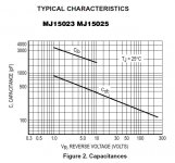
You do all the time they're known as Cje's, Cjs's, Cgs's, etc. They don't have to be C's they could be bad early voltages, quasi-sat. They were conveinient to mention the other day.
Are you really so offended at an educational exercise simply to demonstrate a principle? Are you really incapable of solving the very simple set of equations for the DC output resistance of the high Z node it the JC-3 circuit w/wo the 1Meg resistors? Hint: beta's and early voltages, etc. don't matter to the first order. I said a small envelope, well maybe a big stamp.
The bluster is getting boring, and yes I know you think we need an asylum forum. I promise not to come, you can even ask the mods to ban me.
BTW - mods I don't feel attacked.
Look at those Cj's as Bennie Hill said BIG! Really BIG!
Attachments
Last edited:
What software did you use for schematic capture and simulation ?
In house LTSPICE can do this I'm sure.
jcx - What handles does LTSPICE have to force a rectangular window to work right? Most transient analysis algorithms fly along only worrying about converging to abstol, reltol, etc. When you ask for exact time points they interpolate.
EDIT - Oh BTW the circuit we have been discussing seems to use these bad capacitances as Cdom.
Last edited:
I already posted a fairly nonlinear C model - as Scott mentions you can go the books, look up the equations for semiconductor's junction's C, model I, V dependencies
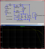
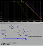
here's another, done in Ltspice
BI source equation is that of a C, behaves in the cirucit sim as a (nonlinear) C
I=(V(x)/20)*200p*ddt(V(x))
"deconstructing" the equation
I = 200p*ddt(V(x))
is the basic behavioral definition of C = 200 pF
you can multiply it by any other function of terminal V, or any other circuit's I or V
you want to avoid negative impedance in compensation C, some equations will do that
the sim actually "subtracts" the BI capacitance from the "real" sim C1
AC sweep shows differing RC corner F with bias V - but you would need a .TRAN sim to see harmonic, IMD distortion
Scott: the fft pop up window has "Binomial smoothing filter applied before FFT and Windowing" length setting in "points" - I'd look on the Yahoo Ltspice users forum for more details
Attachments
Last edited:
reducing bandwidth modulation that leads to PIM,
Can you (or others) please post links to this phenomenon ?
Hi,
I would say that "we" are NOT AMAZED.
I was thinking about an extensive and lengthy reply, but I decided instead to not bother. Life is too short. Grass Mud Horse.
Ciao T
the intent to
I would say that "we" are NOT AMAZED.
I was thinking about an extensive and lengthy reply, but I decided instead to not bother. Life is too short. Grass Mud Horse.
Ciao T
I can post links some others are unlikely to
CordellAudio.com - A MOSFET Power Amplifier with Error Correction
or try a search of Cherry and Otala AES E-Library
CordellAudio.com - A MOSFET Power Amplifier with Error Correction
or try a search of Cherry and Otala AES E-Library
Scott,
Oh, you meant the kind of stuff that would not make a difference if the source impedance was zero and and less of an impact if the drive impedance was lower? Like lower by using a local loop?
Again, if you not mind, how about something REAL, less strawmen?
As my old security team (when I used to run clubs) will attest, I am very hard to offend. You can call me names - any you like - you can even try to throw punches at me. I'm a measely 185cm and 135kg. I can put away a few.
Now what I have an issue with is when we take the concrete into the realm of the imaginary. Why not use a decent capacitor model and a usual not quite so linear output stage (e.g. Keeping it real)?
Given that I have Excel and mathcad on my PC and can grab my old laptop back from my girl (Pspice works on that) as soon as I can convince her to not spend my money on dresses, shoes, handbags and other knck-knacks on line, I suspect, even if I cannot solve them, I have a dog that can.
Well, in first order views everything that makes a sound really does sound the same, so forgive me, but invoking "first order" gets you an F from Thorsten "The Professor" Loesch (the "The Professor" is an old nickname of mine, my best academic qualification is a diploma, but several of them in quite widely distributes areas).
First, I do not bluster. Ever. I never write cheques my a$$ cannot cash.
Second, I NEVER appeal to authority to protect me from bullies.
I simply take them apart instead. And I still dislike strongly having to hit anyone twice, or even once, to be told. Violence or aggression is the resort of the incompetent.
Third, I do happen to believe that we all get more constructive results from a situation within which views that a given "group" has decided to reject (rightly or not and regardless of the reasons) are excluded on demand. It reduces friction. This is self censorship, but sometimes necessary.
In fact, I am by far more happy to help other DIY'ers to get whatever sound they like, then arguing circular with blue meanies about sims that fail to deal with reality.
Neither Do I.
I know a girl (well, nowadays she is more like very old girl) that worked with Benny in the 70's. Trust me, you do not want to bring up Benny.
Ciao T
You do all the time they're known as Cje's, Cjs's, Cgs's, etc. They don't have to be C's they could be bad early voltages, quasi-sat.
Oh, you meant the kind of stuff that would not make a difference if the source impedance was zero and and less of an impact if the drive impedance was lower? Like lower by using a local loop?
Again, if you not mind, how about something REAL, less strawmen?
Are you really so offended at an educational exercise simply to demonstrate a principle?
As my old security team (when I used to run clubs) will attest, I am very hard to offend. You can call me names - any you like - you can even try to throw punches at me. I'm a measely 185cm and 135kg. I can put away a few.
Now what I have an issue with is when we take the concrete into the realm of the imaginary. Why not use a decent capacitor model and a usual not quite so linear output stage (e.g. Keeping it real)?
Are you really incapable of solving the very simple set of equations for the DC output resistance of the high Z node it the JC-3 circuit w/wo the 1Meg resistors?
Given that I have Excel and mathcad on my PC and can grab my old laptop back from my girl (Pspice works on that) as soon as I can convince her to not spend my money on dresses, shoes, handbags and other knck-knacks on line, I suspect, even if I cannot solve them, I have a dog that can.
Hint: beta's and early voltages, etc. don't matter to the first order. I said a small envelope, well maybe a big stamp.
Well, in first order views everything that makes a sound really does sound the same, so forgive me, but invoking "first order" gets you an F from Thorsten "The Professor" Loesch (the "The Professor" is an old nickname of mine, my best academic qualification is a diploma, but several of them in quite widely distributes areas).
The bluster is getting boring, and yes I know you think we need an asylum forum. I promise not to come, you can even ask the mods to ban me.
First, I do not bluster. Ever. I never write cheques my a$$ cannot cash.
Second, I NEVER appeal to authority to protect me from bullies.
I simply take them apart instead. And I still dislike strongly having to hit anyone twice, or even once, to be told. Violence or aggression is the resort of the incompetent.
Third, I do happen to believe that we all get more constructive results from a situation within which views that a given "group" has decided to reject (rightly or not and regardless of the reasons) are excluded on demand. It reduces friction. This is self censorship, but sometimes necessary.
In fact, I am by far more happy to help other DIY'ers to get whatever sound they like, then arguing circular with blue meanies about sims that fail to deal with reality.
BTW - mods I don't feel attacked.
Neither Do I.
Look at those Cj's as Bennie Hill said BIG! Really BIG!
I know a girl (well, nowadays she is more like very old girl) that worked with Benny in the 70's. Trust me, you do not want to bring up Benny.
Ciao T
Can you (or others) please post links to this phenomenon ?
Find Barrie Gilbert's article on Jan's site. He uses a simplified model for educational purposes so some won't like it.
Hi,
Of course you can. But did you actually bother to READ them? Including the marginal notes covering scope and applicability.
Ciao T
I can post links some others are unlikely to
Of course you can. But did you actually bother to READ them? Including the marginal notes covering scope and applicability.
Ciao T
- Status
- Not open for further replies.
- Home
- Member Areas
- The Lounge
- John Curl's Blowtorch preamplifier part II