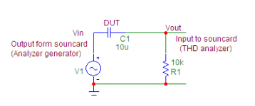
What i did is in picture. I do not know, if test was "to easy", but for sure was realistic if one wants to use capacitor as coupling, to remove some DC ofset in non power stages. And used capacitor(s) is one fom batch of 1000 pcs, price about 2c. Ordinary radial 10u/50V. Measured was THD (spectra), no DA or so..If you did what you stated, then you either had a very good cap, or the cap was not 'working' within the bandwidth that you measured, or the test was too 'easy'. This can be shown with Walt's and my paper where I tested a 10uF ? aluminum cap against an 8uF ? Rel. polypropylene with a nominal 50K load. I got, (best case) 0.19% or about -54dB. This is with just ONE CAP! And by canceling any ideal or static characteristics of the cap on test.
In diference test was this elyt (in+in chain) compared to 10u MKT cpacitor (in -in chain).
Attachments
Last edited:
BV until you read Walt Jung's and my paper, you will be in the dark about what we measured, and its implications. In one case I used a 10uF cap and a 50K load, even easier than yours, AND I got 0.19%, or 54 dB, where is YOUR error? If you have no error, then what are you doing different than an idealized subtraction test?
So far as I know, DA will show up in a differential subtraction test as easily as any nonlinear distortion, or THD will. Therefore a null should be difficult if a common input coupling cap is put in series with an amplfier under test, unless something is done to 'nullify' the cap's DA. This is possible by using a nonlinear cap as a subtracter, but the results will be useless, because the DA distortion will reappear when the unit under test is used normally.
What I did (difference test)is here, http://www.diyaudio.com/forums/anal...ch-preamplifier-part-ii-1503.html#post2673998,
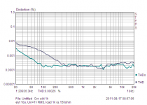
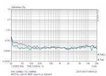
results in post before. DA will show (as THD) only if here is some voltage across capacitor, as is obvious from following pictures. No errors, real results, coresponding to well known facts.
results in post before. DA will show (as THD) only if here is some voltage across capacitor, as is obvious from following pictures. No errors, real results, coresponding to well known facts.
Attachments
Last edited:
As is clearly writen here,
http://waltjung.org/PDFs/Picking_Capacitors_1.pdf just at first side,
"capacitor will generate distortion if here is AC voltage dropped across..." And V test was 3V RMS, load 680 ohm, so. This is the same result, as I posted, no difference.
Conclusion is simple, we should use "big enough" value for coupling capacitor, and we can forget distortions added by capacitor in this position. Using e. g. ceramic capacitor in LP filter (exposed to full AC swing)is something quite different.
Last edited:
I'm not sure why it is felt necessary to occasionally lob into the discussion a 'grenade' from Russian science which allegedly undermines current (Western?) audio engineering. So far, the grenades haven't gone 'BANG' but just 'poof'. The nice thing about maths is that Russian maths has to be the same as maths everywhere else, so correct maths correctly applied is valid everywhere. The theoretical underpinnings of audio engineering are quite safe, although often misunderstood by people who don't get maths.
At the university , in Strasbourg , France , the most useful and recommended course of maths for engineering domains was a russian book , by I.N Bronstein and K.A Semendiaev , wich i still currently have....
")
Soviet Union was simply more advanced in mathematics ,alas, due to cold war , Soviet scientists and engineers were not known at all in western world, apart from celebrities like Kolmogorov, and still , only in a little circle.
Reference subtraction caps should be Teflon, polypropylene, or polystyrene. Everything else is suspect.
John, in the paper dd 1995, Hawksford measured distortion of a simple peace of copper wire, with the aim of choosing optimum diameter.
The distortions are not measurable with continuos signal, it is revealed only at the moment of sharp transient, when the input signal is cut abruptly. An extra-tail is visible at the output, compared to input.
I guess, for testing caps, again, it would be correct to use a single pulse test. Comparing input and output pulses, one should also decide, how he should quantify the difference. I do not believe, that comparison of the spectra is applicable in this case.
The pdf is too big, I give here a reference to the paper
"Stereophile, October 1995. The Essex Echo. M.O.Hawksford Examines Electrical Signal Propagation And Explores The Implications For Audio Cable Performance."
Last edited:
And what about inductance?? Short piece of straight wire is not "inductanceless". Sharper transients, more overshoots..The distortions are not measurable with continuos signal, it is revealed only at the moment of sharp transient, when the input signal is cut abruptly. An extra-tail is visible at the output, compared to input.
And what about inductance?? Short piece of straight wire is not "inductanceless". Sharper transients, more overshoots..
It can be inconvenient for us, but just similar effects, being revealed with non-symmetric non-periodic signals, play more role, than the sine test. Including all parasitic tiny inductances, caps residual effects due to DA, effects of insulation materials etc.
With the single-pulse test, imperfections of caps is much more visible.
Last edited:
It is not about convenience, but about some technical background and acceptance of validity of known physical principles. The are valid also in HighEnd ,too .
And I am very curious, what effect on perceived sound should have sharp transient effects with duration in nsec or usec in electric signal..Which transducer and ears can it radiate and analyse ?
And I am very curious, what effect on perceived sound should have sharp transient effects with duration in nsec or usec in electric signal..Which transducer and ears can it radiate and analyse ?
Yes, I agree. When I was an undergraduate the standard recommended textbooks on the classical theory of fields were written by two Russians. I was not criticising Soviet science, but an apparent attempt to derail discussion by misunderstanding it or misapplying it.wahab said:Soviet Union was simply more advanced in mathematics ,alas, due to cold war , Soviet scientists and engineers were not known at all in western world, apart from celebrities like Kolmogorov, and still , only in a little circle.
On capactor tests, I though we had already agreed that DA is not distortion - it is linear. It may be a marker for less desirable dielectric properties, but on its own it does not produce distortion but just some minor LF response changes.
On capactor tests, I though we had already agreed that DA is not distortion - it is linear. It may be a marker for less desirable dielectric properties, but on its own it does not produce distortion but just some minor LF response changes.
In some circles it was agreed, and it is quite OK for members of these circles. They also like to play with a bit simplified models of amps.
In other circles, it is agreed, that continuous sine test is almost useless, and if a pulse test show distortion artefacts due to DA, this is a big trouble for members of these other circles. In spite that an amp, containing such distorting caps, can be quite a perfect with sine test.
In the third circles, people simply say, that nobody still understand audio on the strict scientific basis, and believe only to their hearing, and pay for equipment on this ground.
In the fourth circles, containing managers and advertising personnel of big audio manufacturers, it is considered that major part of buyers must not have any doubt as per level of equipment proposed to them, and the more solid grounds have THD criterion, the more income goes to mass manufacturing companies. They would even support, that this axiom would be fixed in people's mind at the stage of their education.
You missed a circle. People in this circle avoid the mistakes made in the four circles you described. They are not naive (circle 1), ignorant (circle 2), rich and ignorant (circle 3) or manufacturers (circle 4).
So you imply that I missed a circle of "knowing the truth".
OK, let us believe that it exists.
Hope that members of this circle will proove their status by demonstrating divine sounding amps, and not draw us to dead end.
No, you don't need any voltage across the capacitor to show DA in a difference test. IF people would only read our paper, you would find out how to measure a cap (optimally) to show DA. Sine wave analysis will show ONLY very minor phase shift. But then, we were looking for measurable differences, not trying to prove that differences are not significant. That meant that we had to find a test signal that was 'reasonable worst case' to bring out the DA, which we did. Even Dr. Lipshitz agreed that our math and measurements were correct. Hawksford criticized the fact that I had omitted the inductive correction, but I had deliberately BANDWIDTH LIMITED the test waveform to remove any significant contribution of any reasonable inductive component when conducting he test.
John, you're right; if the goal of the test is to measure DA, your test is more appropriate. If the goal is to find out if a cap will cause distortion when used for coupling, BV's test is more appropriate. I would probably want the measurement repeated at very low frequencies to see if the cap causes bass distortion when the voltages across it are greater. If I can get time tonight, I'll show the same sort of measurement at several different frequencies.
- Status
- Not open for further replies.
- Home
- Member Areas
- The Lounge
- John Curl's Blowtorch preamplifier part II