Hi,
Toshiba for sure. But I suspect if you look closer you find one is a 2SK389 used in the DC Restorer (aka DC Servo) and the other 2SJ109 used in the "Distortion Extraction Amp".
It is a few years ago I saw the more detailed schematics in MJ, so things are a wee but hazy (my memory ain'f what it used to be, then again, it never was anyway)...
The main forward part are AC coupled Bipolars in parallel with Cascode, the bit on top is actually a current mirror (possibly with gain), this directly drives tripple Darlington outputs. The "other side" of the current mirror is a simple resistor, so local degeneration and loads set the gain overall. No global feedback, output stage runs as very overbiased Class AB. Such an Amp easily can do < 0.1% THD at 1W and < 0.5% THD at full power, 20KHz.
The DC restorer is linked into the forward path, with quite low gain and has a long timeconstant.
The Error Amp is a simple P-Channel Differential, cascoded and current mirror loaded if memory serves. One input gets the input signal, the other the scaled output (this probably needs adjustment of very precise resistors setting gain everywhere and massive amounts of degeneration in the forward path). The output of this "distortion extractor" is an Emitter follower that drives the load resistor for the open loop VAS.
Looking at the distortion gain in the distortion feedback circuit, there is maybe 30dB gain, so distortion is lowered by that amount, the degree of correction this circuit is capable off is quite small, however, even if it saturates, the open loop forward path will scarecly care and keep working at increased THD, but no clipping, sticking, TIM etc....
I would have probably used J-Fets for the Input stage and lateral mosfets for the output (especially with 60W/8R Class A operation, but that's just me...
Ciao T
Nope , toshiba custom SIP . Same as the JVC super A , custom manufactured for luxman.
Toshiba for sure. But I suspect if you look closer you find one is a 2SK389 used in the DC Restorer (aka DC Servo) and the other 2SJ109 used in the "Distortion Extraction Amp".
It is a few years ago I saw the more detailed schematics in MJ, so things are a wee but hazy (my memory ain'f what it used to be, then again, it never was anyway)...
The main forward part are AC coupled Bipolars in parallel with Cascode, the bit on top is actually a current mirror (possibly with gain), this directly drives tripple Darlington outputs. The "other side" of the current mirror is a simple resistor, so local degeneration and loads set the gain overall. No global feedback, output stage runs as very overbiased Class AB. Such an Amp easily can do < 0.1% THD at 1W and < 0.5% THD at full power, 20KHz.
The DC restorer is linked into the forward path, with quite low gain and has a long timeconstant.
The Error Amp is a simple P-Channel Differential, cascoded and current mirror loaded if memory serves. One input gets the input signal, the other the scaled output (this probably needs adjustment of very precise resistors setting gain everywhere and massive amounts of degeneration in the forward path). The output of this "distortion extractor" is an Emitter follower that drives the load resistor for the open loop VAS.
Looking at the distortion gain in the distortion feedback circuit, there is maybe 30dB gain, so distortion is lowered by that amount, the degree of correction this circuit is capable off is quite small, however, even if it saturates, the open loop forward path will scarecly care and keep working at increased THD, but no clipping, sticking, TIM etc....
I would have probably used J-Fets for the Input stage and lateral mosfets for the output (especially with 60W/8R Class A operation, but that's just me...
Ciao T
Nobody's interested? It's a pretty elegant little circuit element that includes a differential input (and output, if needed), good power supply rejection, low noise, yada yada. Not practical for monolythic IC's because requires device matching and many volts headroom.
I've come to see it as a natural offshoot of the John Curl input stage, and its complement in many ways. But if nobody's interested.....
I've come to see it as a natural offshoot of the John Curl input stage, and its complement in many ways. But if nobody's interested.....
stop teasing; of course we are interested!
")
mlloyd1
mlloyd1
Nobody's interested? It's a pretty elegant little circuit element that includes a differential input (and output, if needed), good power supply rejection, low noise, yada yada. Not practical for monolythic IC's because requires device matching and many volts headroom.
I've come to see it as a natural offshoot of the John Curl input stage, and its complement in many ways. But if nobody's interested.....


A question about JFETs in general, and those from Toshiba / Linear Systems in particular.
Many JFETs (including those from NXP and Sanyo) are symmetrical, i.e. the drain and the source can be swapped.
I have tried this on BF862, e.g., and it works perfectly.
Does this also apply to the likes of 2SK170s or LSK170s ?
Or any JFETs for that matter ?
Patrick
Many JFETs (including those from NXP and Sanyo) are symmetrical, i.e. the drain and the source can be swapped.
I have tried this on BF862, e.g., and it works perfectly.
Does this also apply to the likes of 2SK170s or LSK170s ?
Or any JFETs for that matter ?
Patrick
You are right.
I was curious, and remembered that I had a few samples lying around.
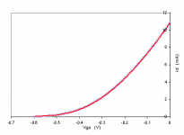
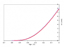
So I measured one of each.
LSK170 is not quite identical when reversed.
Left (11mA Idss) is 2SK170.
Red line is as per datasheet. Blue crosses are D-S reversed.
Patrick
.
I was curious, and remembered that I had a few samples lying around.
So I measured one of each.
LSK170 is not quite identical when reversed.
Left (11mA Idss) is 2SK170.
Red line is as per datasheet. Blue crosses are D-S reversed.
Patrick
.
Attachments
Last edited:
Any comments on the topology above?
An obvious limitation is the difficulty in degenerating transconductance enough for a no-long-loop-feedback line stage. Much more suited for a phono equalizer or a conventional loop-fedback line stage.
The cascoding is important both for linearity and for power supply immunity because inputs are referenced to supply rails.
I've never seen this in print, but probably *somebody's* thunk it up before. Any previous mentions would be appreciated. Thanks,
Chris
The resistor with ?? marks just came to me
Without the resistor, very little happens.
Without the resistor, very little happens.
The resistor allows adjustment of transconductance independent of quiescient current. If the resistor is not there there is no gain at all.
My earlier pictures were terrible, so maybe these will help show signal polarities that are causing my heroes some consternation.


Figure 1 is a simplified John Curl input stage, drawn to emphasize its four quadrants. Figure 2 shows it divided in half and is redrawn in figure 3, diff-in single-ended-out. Figure 4 is the top half of figure 3 doubled for diff-in and diff-out, including the (bad idea, sorry) ?resistor. Redrawn for clarity in figure 5. Figure 6 is a simplified high gain topology drawn with the cascodes that keep it linear. The source degeneration resistors in the second ("VAS") stage must be chosen for proper DC conditions leaving transconductance to you'll-get-what-you-get-and-like-it. Hoping someone might see a way around that foible. Thanks very much for any comments.
Figure 1 is a simplified John Curl input stage, drawn to emphasize its four quadrants. Figure 2 shows it divided in half and is redrawn in figure 3, diff-in single-ended-out. Figure 4 is the top half of figure 3 doubled for diff-in and diff-out, including the (bad idea, sorry) ?resistor. Redrawn for clarity in figure 5. Figure 6 is a simplified high gain topology drawn with the cascodes that keep it linear. The source degeneration resistors in the second ("VAS") stage must be chosen for proper DC conditions leaving transconductance to you'll-get-what-you-get-and-like-it. Hoping someone might see a way around that foible. Thanks very much for any comments.
Hi,
I like the use of the Rush Cascode. In order to gain more control about the transconductanceone might deliberatly add some DC between the two gates of the Rush Cascode (tapping the resistors) to either minimise or maximise transconductance, however, I not necessarily see this as being appreciably superior to John Curls original topology shown below.
Ciao T
View attachment 228820
Figure 6 is a simplified high gain topology drawn with the cascodes that keep it linear. The source degeneration resistors in the second ("VAS") stage must be chosen for proper DC conditions leaving transconductance to you'll-get-what-you-get-and-like-it. Hoping someone might see a way around that foible. Thanks very much for any comments.
I like the use of the Rush Cascode. In order to gain more control about the transconductanceone might deliberatly add some DC between the two gates of the Rush Cascode (tapping the resistors) to either minimise or maximise transconductance, however, I not necessarily see this as being appreciably superior to John Curls original topology shown below.
Ciao T
Attachments
Hi,
I like the use of the Rush Cascode. In order to gain more control about the transconductanceone might deliberatly add some DC between the two gates of the Rush Cascode (tapping the resistors) to either minimise or maximise transconductance, however, I not necessarily see this as being appreciably superior to John Curls original topology shown below.
Ciao T
I don't particularly like the asymmetry of the second stage, what goes up and what goes down are no longer one in the same.
Last edited:
Some sad news about two gentlemen whose names have appeared in this thread. I didn't know them personally, but I'm sure many of y'all did. I'm sorry for the loss.
Analog guru Jim Williams dies after stroke - 2011-06-13 15:26:32 | EDN
http://www.edn.com/article/518568-Analog_engineering_legend_Bob_Pease_killed_in_car_crash.php
Analog guru Jim Williams dies after stroke - 2011-06-13 15:26:32 | EDN
http://www.edn.com/article/518568-Analog_engineering_legend_Bob_Pease_killed_in_car_crash.php
- Status
- Not open for further replies.
- Home
- Member Areas
- The Lounge
- John Curl's Blowtorch preamplifier part II