I assume this was to me...if not, oh well, I'm answering anyway.Audio transformers are wound with hair thin wire - are you saying that the wniding wire exhibits skin effect change in resistance over the audio band ?.
Ditto, are you saying that the core materials change resistance according to frequency also.
Eric.
An interesting question.
The guage of wire is sufficiently low that normal skin effect won't be a problem. Most consider skinning based on that exponential approximation equation, with some depth associated with the conductor at some frequency.
However, we've been talking about proximity effect also. Proximity effect is the current being forced to one side of the conductor as a result of the overall field present in the coil. For a very small coil with lots and lots of turns, the magnetic field present on the inner turns of the coil is significantly larger that a single wire field would be, so this enhanced field can still force the current to move to one side of the wire.
It would require a lot of computing horsepower to do the analytical computation needed to find the rise in resistance. We've done it here lots using roxio or opera (not sure which), but it takes half a day to do one iteration..
As for core materials changing resistance with frequency, I'm not sure about that one. Core losses will increase if you increase the rate of change of the flux within it, but that is not the same as lowering the core resistivity.
It is far more reasonable to just use a good meter to determine Ls-Rs over the frequency band of interest, and use the effective resistance vs frequency as the metric.
ps...JC, ya shoulda waited..
Cheers, John
Last edited:
Yes, precisely. The mechanism (magnetic induction, resistive losses) is present, whether it is being driven by a signal or not. This is all you need for thermal noise. I know you can't accept this, but it is true. It is not the fact that eddy currents are currently dissipating energy which creates the thermal noise, but that the mechanism is present and the noise source (the core) is at a non-zero temperature and therefore will have thermal fluctuations.jneutron said:If there is no primary current, there is no net flux in the core. No net flux, no rate of change of flux. No rate of change of flux, no eddies. No eddies, no eddy losses.
To accept what you are saying, a mechanism which is capable of eddy current dissipation without any current flowing through any of the terminals MUST be present.
Take a transformer (or a choke). Connect it to an amplifier or meter, so you can hear/measure noise. Just before you do this, measure the DC resistance and the AC resistance at some appropriate frequency/ies. Measure the noise voltage, and heat the core while trying to avoid heating the windings (not easy, but it will take a while for heat to transfer between them so be quick). You should see the noise increase. Quickly repeat the DC and AC resistance measurements. Measure/estimate the core temperature. Measure/estimate the winding temperature (possibly from any rise in DC resistance). Calculate the thermal noise from the given resistances and temperatures (assume that winding resistance is unchanged from the DC value?). Compare with noise measurements.
Not an easy test, but it is the best I could think of to show the effect. The idea is to show that raising the core temperature increases noise, both by raising the corresponding resistance and raising the temperature of that resistance.
Yes, precisely. The mechanism (magnetic induction, resistive losses) is present, whether it is being driven by a signal or not.
You are basically saying that there will be eddy losses despite there being no magnetic flux rate of change present.
You will have to provide a mechanism to explain that.
This is all you need for thermal noise. I know you can't accept this, but it is true. It is not the fact that eddy currents are currently dissipating energy which creates the thermal noise, but that the mechanism is present and the noise source (the core) is at a non-zero temperature and therefore will have thermal fluctuations.
The coil integrates all the rate of change of flux passing through it. Heating a core does not provide a rate of change of flux through the core.
blue comments interspersed again..for clarification
Take a transformer (or a choke). Connect it to an amplifier or meter, so you can hear/measure noise. Just before you do this, measure the DC resistance and the AC resistance(measures all losses, wire and core eddies) at some appropriate frequency/ies. Measure the noise voltage, and heat the core while trying to avoid heating the windings (not easy, but it will take a while for heat to transfer between them so be quick). You should see the noise increase.(this is the crux of our disagreement, and is pretty much exactly the test I recommended with 4 different core types, a thousand postsor so ago..) Quickly repeat the DC and AC resistance measurements. (Here, you are driving eddy current losses on a hot core, and it's resistivity will now be different, this is a confounder that cannot be neglected..)Measure/estimate the core temperature. Measure/estimate the winding temperature (possibly from any rise in DC resistance). Calculate the thermal noise from the given resistances and temperatures (assume that winding resistance is unchanged from the DC value?). Compare with noise measurements.
Not an easy test(you are a master of understatement..
It would be better to do the 4 core test, as it changes in essence, the eddy loss component only. Honestly, what Scott mentioned is the better test...drive the coil using a variable sine, and look for sidebands.
Cheers, John
Heres some good (if simplistic) papers from Dr. Sullivan et al, of Dartmouth.
I hope the links work.
note: Odd that he refers to an HP 4284 as a network analyzer, yet the manual 4 feet away from me says "precision LCR meter".
This paper has a gapped core 1500 turn #36 AWG measurement. Note that he discusses gapped cores as well in section IV. Gapped cores reduce the inductance, but more importantly, it increases the proximity losses of the wires that are close to the gap. He has some other papers on his site which detail optimum wire locations within a gapped core vs frequency, but that's something I'd recommend only for interested parties..
http://engineering.dartmouth.edu/inductor/papers/sfdj.pdf
Here is a light paper describing the lowering of the relative permeability of round wire winding. This is basically a discussion of how the conductor reacts to the time varying flux the wire is embedded in. It is exactly what happens as well, when I put a half inch thick aluminum plate into the magnet gap..
http://engineering.dartmouth.edu/inductor/papers/perm.pdf
Here is an easy read paper, the first page has some good pictures of the difference between skin effect and proximity effect..what I like is, it is extremely close to what occurs in my superconducting wires and magnets..very cool...
http://engineering.dartmouth.edu/inductor/papers/litzcj.pdf
Cheers, John
ps...the use of the terms "simplistic" and "easy read" are most certainly tongue in cheek..hey, ya gotta have fun...
pps..note that MY referred papers are from this century...thank you very much....
Last edited:
There will be the mechanism. The flux will be changing due to thermal fluctuations in the core. The average flux (averaged over infinite time) will be zero. Average over any finite time and you get some net flux - the shorter the time the larger the net flux. You also need to average over all the lams, but the same principle applies. Each lam contributes a small amount of thermal power, so you add the power not the flux (flux adds as root mean squares).jneutron said:You are basically saying that there will be eddy losses despite there being no magnetic flux rate of change present.
I guess the ideal test would be a hot core and superconducting winding! That would guarantee no thermal noise from the winding itself, just the core.
I agree that the test with identical windings and different cores would be easier. The difficulty might be ensuring that lam thickness was the only variable.
There will be the mechanism. The flux will be changing due to thermal fluctuations in the core. The average flux (averaged over infinite time) will be zero. Average over any finite time and you get some net flux - the shorter the time the larger the net flux. You also need to average over all the lams, but the same principle applies. Each lam contributes a small amount of thermal power, so you add the power not the flux (flux adds as root mean squares).
Average over any finite time?? Like picoseconds averaged over square nanometers?
Please detail exactly what net flux is available more than 100 nanometers from the surface of the core. Then detail exactly how that net flux is aligned with the core such that the coil sees a net flux passing through the windings.
Remember that the coil is not capable of generating an induced voltage as a result of infrared radiation. Yes, it can get hotter, but we're considering that as a considered/controlled entity. So you must provide a mechanism which produces time varying flux within the audio band that is positioned/focussed such that it travels through the coil to be picked up as a net rant of change of flux. Until you can provide that mechanism, the assumption that magnetic energy generated by thermal atomic motion within the core can create a magnetic field capable of pickup within the coil...is an unfounded assumption. (in my humble oinion..)
I guess the ideal test would be a hot core and superconducting winding! That would guarantee no thermal noise from the winding itself, just the core.
And the 4 kilowatt cryopumps...
I agree that the test with identical windings and different cores would be easier. The difficulty might be ensuring that lam thickness was the only variable.
When I first provided the mechanism of eddy current losses making noise, I explained in detail what the mechanism was, how it acted, and VERY importantly, I provided a test designed to expicitly prove or disprove the validity of my assertions. Scott provided the sideband content as a good metric, as I would have been left with looking at a high voltage sine for a hint of noise.
So far, I've seen no doable test which comes close with fewer confounders. Perhaps it would pay to do my test..
Cheers, John
Last edited:
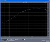
OK, I'll waste a little time on this today just to give us something tangible to talk around. Here is a spectrum of the open circuit noise of the worst tape head I could find (VHS audio track). DCR = 385 Ohms somewhere around -102dB on my plot. Ok where does the noise at 10k come from? It's almost 6-7K Ohms equivalent.
EDIT - Hate to dissapoint the "cores don't work through zero guys" but the noise has a perfect gaussian amplitude distribution even at this nano-volt level.
EDIT - Hate to dissapoint the "cores don't work through zero guys" but the noise has a perfect gaussian amplitude distribution even at this nano-volt level.
Attachments
Last edited:
Remember that the coil is not capable of generating an induced voltage as a result of infrared radiation. Yes, it can get hotter, but we're considering that as a considered/controlled entity. So you must provide a mechanism which produces time varying flux within the audio band that is positioned/focussed such that it travels through the coil to be picked up as a net rant of change of flux. Until you can provide that mechanism, the assumption that magnetic energy generated by thermal atomic motion within the core can create a magnetic field capable of pickup within the coil...is an unfounded assumption. (in my humble oinion..)
Equipartion theorem, the thermal phonons exchange energy with the carriers.
The carriers generate flux and by the central limit theorem the net flux is zero has a noise determined by its temperature.
Equipartion theorem, the thermal phonons exchange energy with the carriers.
The carriers generate flux and by the central limit theorem the net flux is zero has a noise determined by its temperature.
So take it further. Integrate the net flux which is capable of going through the core.
Then take it even further.. consider the difference between laminate thicknesses. They are nowhere near atomic dimensions, so will integrate to net zero at a small scale, many orders of magnitude below the dimensions we speak of for laminate thicknesses.
As I said before, 4 core testing is the way to go..
Cheers, John
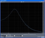
OK, I now resonate the head with a nice 33nF polystyrene cap. Oh oh, more splain'in to do. I claim there is enough information here to derive all the needed parameters. Ed this was my experiment. I don't have time right now to calibrate these measurements well enough to extract exact numbers. That is from the resonant frequency I have L, from the Q I can can derive a series or parallel model and I bet the equivalent Rs at 2KHz is > 385 Ohms. It's actually complicated by the fact that duplicating this plot in SPICE would require Rs, L, and a frequency dependent Re and you would need to piece this plot together frequency by frequency.
Attachments
Last edited:
No, I did not reveal what G means....gotcha..
I've not yet read the paper linked, but I did find reference to the transatlantic cable and mu metal...what a fascinating read on some vendor site. For a while, the largest user of mu metal was just for these cables.. They mentioned the seawater (but not G)and capacitance which required the mu, so cool..
Cheers, John
A few items:
You began to bring up characteristic impedance. That is what the R value in a properly designed cable yields. When the driving source and load impedance match no power is reflected from either end. On a 2200 mile cable a bounce would take 4400 miles, allow for some reduced velocity of propagation compared to a vacuum that would be 25 or so milliseconds. Enough to cause problems even with fast Morse Code. Today we use the ratio of the inner conductor to the outer conductor to determine the value. This clearly is a factor above 200,000 cycles per second. It is an interesting issue if it is of importance in analog audio.
Before jargonistic labels were applied magnetic field was quantified in "Lines of Force." That made it easier for the novice to follow what is going on.
When the lines of force intersect out magnetic material the influence depends on the angle of intersection. I believe this follows the cosine of the angle SQUARED! That will have some influence on the generation of noise from thermal issues in real inductors.
The discussion has been on audio transformers as this is the Blowtorch thread JC has mentioned he used the Signal transformer flatpack style oc C I cores. These have a number of interesting properties such as lower bandwidth than E I cores. They also use thicker laminations. There are two primary coils that are wound next to (not over) the secondaries. Is it possible for this configuration to allow both coils inside windings to go to the neutral? Is this done?
ES
I mentioned Porsches, because my other Porsche is a 911. (remote controlled toy model, that is). And to think that you wanted a discount on Toshiba parts, Jam. Tsk, tsk, you should be kinder to your elders. What would I do with a full power 911, NOW that I am half blind?
Do You See What I See?: Memoirs of a Blind Biker
Amazon.com: Do You See What I See?: Memoirs of a Blind Biker (9781571745590): Russell Targ: Books
If your measurement bandwidth is, say, 10Hz then average over 0.1s. If your core size is, say, 1cm^3 then average over that volume.jneutron said:Average over any finite time?? Like picoseconds averaged over square nanometers?
Please detail exactly what net flux is available more than 100 nanometers from the surface of the core. Then detail exactly how that net flux is aligned with the core such that the coil sees a net flux passing through the windings.
Exactly that flux which will induce a voltage in the windings equal to the thermal voltage of the reflected resistance due to eddy current losses. Calculating back from the expected thermal power is the easiest way to do it. As the winding encloses the core the issue of flux above the surface does not arise. The engineers' picture of lines of flux cutting a winding may helps with visualisation, but the correct method involves surface and line integrals - a surface integral of the flux threading the winding gives the voltage induced along a line integral around the winding (curl E = dB/dt). However, I must admit that my EM theory is rusty these days.
No, thermal electronic motion. Remember, it was electrons moving which dissipated the energy so it must be electrons moving which create the noise.magnetic energy generated by thermal atomic motion
You keep asserting that there can be no net flux, and keep asking me to provide the mechanism for this. I (and others who know some physics) keep telling you that you are mistaken, and that thermal fluctuations are the mechanism. How many times do we have to go around this circle? I explain some standard physics, you deny it. It is not me you are arguing with, but physics!
I don't know what else to say, as you don't seem to understand thermal fluctuations. Please forgive my bluntness.
OK, I now resonate the head with a nice 33nF polystyrene cap. Oh oh, more splain'in to do. I claim there is enough information here to derive all the needed parameters. Ed this was my experiment. I don't have time right now to calibrate these measurements well enough to extract exact numbers. That is from the resonant frequency I have L, from the Q I can can derive a series or parallel model and I bet the equivalent Rs at 2KHz is > 385 Ohms. It's actually complicated by the fact that duplicating this plot in SPICE would require Rs, L, and a frequency dependent Re and you would need to piece this plot together frequency by frequency.
As a friend used to say when these kinds of issues came up, "Sorry I can't comment it is not my area." That was much nicer than "You are getting interesting results but I ethically can't say anything." It also never required follow up.
As a friend used to say when these kinds of issues came up, "Sorry I can't comment it is not my area." That was much nicer than "You are getting interesting results but I ethically can't say anything." It also never required follow up.
I also have to factor out the input impedance of my mike input on my sound card or build the little FET buffers I mentioned. The buffers will make prettier pictures, no math to fake it. A few items:
You began to bring up characteristic impedance.
Not on purpose...I just put up the equations becker had. The R in what I posted is not cable Z, it is resistance per unit length. Apparently, when you use a cable which has lossy conductors, and capacitance with "leakance" to use becker's word, you have to make those two terms equal to minimize damping. Thusly, the result is that the propagation frequency becomes constant across the fequency band of interest. Otherwise, the high frequency content will arrive at a different time from the low frequency content, hence the distortion.
Now it's flux tubes, pinning sites, yada yada..yada...Before jargonistic labels were applied magnetic field was quantified in "Lines of Force." That made it easier for the novice to follow what is going on.
Cheers, John
As usual someone else has done the homework and we can copy it.
http://products.midcom-inc.com/Tech/pdf/tn82.pdf
http://products.midcom-inc.com/Tech/pdf/tn82.pdf
- Status
- Not open for further replies.
- Home
- Member Areas
- The Lounge
- John Curl's Blowtorch preamplifier part II