Yeah, my 5.0 wasn't bad for just eyeballing off a jpeg image. And my actual measurement was 4.9 and some change I just rounded it up to 5 even. I wasn't looking at this in terms of intermod frequencies, but simply making relative measurements in inches based on fig. 3.
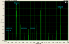
By the way, here are the approximations of all the unlabeled peaks in fig. 3.
An externally hosted image should be here but it was not working when we last tested it.
se
Hi Steve,
Thanks for your effort here. This is very close to my earlier assertion that the frequencies were 2f2-9f1 = 1380 and 11f1-2f2 = 4980.
Throughout this exercise, we all must be mindful that this is not a high fidelity measurement by any stretch of the imagination. The Figure 3 example is pounding the cr@p out of a known cr@ppy op amp.
It would be far more interesting to see the same results for a modest-fidelity modern op amp under the same conditions. Maybe something like an OPA-604.
It is not the least bit surprizing that this kind of amplitude spectra can be created by fm modulation, but that only underscores the fact that with amplitude spectra alone it is virtually impossible to discriminate between TIM and PIM. It in no way supports the assertion that these sidebands show that there is PIM.
Cheers,
Bob
Hi Anatoliy,
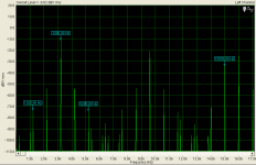
With FM modulation, you get a continuous spectrum. With square wave modulation that is working perfectly, you will get what is called FSK, or frequency shift modulation. The only time you will have a discontinuous spectrum with FM that I know of is if you are sampling in some way. However, the center frequency (or carrier) is changing continuously between the peak high extreme and the peak low extreme of the deviation, or change in frequency. That continuous sweep back and forth "looks" like a continuous spectrum. I'm looking at an FM IF sweep right now, here it is.
Notice that it is continuous in nature. The input is a swept 10.7 MHz center, 800 KHz range. In other words, the high frequency is 10.7 MHz and the low frequency (modulation) is 5 Hz (inverse of sweep time). My earlier post showed 10.7 MHz modulated by 1 KHz, so take your pick from these. I can, and later will, try with the lower frequencies that this thread is concerned with. I don't have time right now and the generator I'm using (HP 8656B) only goes down to 100 KHz. I'll need to use an HP 3324A and 3336B in order to recreate the exact test setup used by John. That is why I have been asking for his test setup - so I can see what he is seeing.
Modulation in a linear analog power amplifier will be AM for the most part, FM modulation is what I think they are looking for, and may occur at very low modulation depths. Can you imagine listening to an amplifier that is being modulated using FM? That might be somewhat like listening to a turntable suffering from wow and or flutter. A frequency effect hard to miss.
Chris; you are right about sampling rate. Imagine very fast sampling when you amplitude modulate the signal. Do you see sidebands? No. Each measurement you take such a way show you the signal of the same frequency, but of a different amplitude. Similarly, when you observe FM such a way you see as if it is the single sinewave signal with slightly different frequency. But it is not what you see on a spectrum analyzer. Here is the picture of sidebands of FM (however, -180 degrees are not shown):
An externally hosted image should be here but it was not working when we last tested it.
I've found this picture for you googling for FM sidebands:
http://www.radio-electronics.com/in...-frequency-modulation/what-is-fm-tutorial.php
Edit: you may see that for FSK you've mentioned bandwidth will be needed is double deviation plus double baud rate. I.e. if you limit bandwidth of transmitter and receiver by double deviation you won't be able to transmit FSK.
Also, you may search for phase modulation methods to obtain SSB. They were (and are) still used in radio. The plus is, they don't require expensive mechanical filters, and such SSB modulators can be micro-miniaturized.
Last edited:
Wavebourn, .5 looks pretty good to me, for this. What do you think?
About what?
If you mean how nasty sounds mixed phase and amplitude intermodulation, I think you may get an impression listening to SSB transmission on AM receiver.
By the way, here is a SSB modulator designed by Russian ham radio operator A. Polyakov (RA3AAE), you see how it is easy to get a nasty SSB sound just summing clean and phase modulated signals (that happens in opamp-based amps easily):
Steve, I had an appointment with Jan Lohstroh today and took the opportunity to go through his files from way back. Came up with this:
http://www.linearaudio.nl/Miscellaneous/espoo 1976.pdf
I haven't gone through it in detail, just scanned and posted it, but it does offer some other perspectives on the DIM method and results.
jd
Sorry, Jan! I missed this the first time around and only just caught on what your bump post was about.

Thanks for providing the article. Though I really don't want to get in to the whole TIM/DIM/PIM debate.
It's just that y'all were arguing over what was shown in fig. 3. You'd previously labeled some of the peaks in it, and John questioned whether or not they were accurate.
So I thought I'd use some of my CAD/graphics skills to get a better fix on what frequencies the unlabeled harmonic components were.
se
Hi Anatoliy,
Thank you, I am very familiar with modulation types.
Now, just above the pictures you posted for us, there is some text that I feel is relevant and important to consider.
First, an infinite series of frequencies (Fourier equivalent of a square wave) all modulated together by a since wave. Man, that's some kind of spectral mess you'll have there!
Second, a sine wave modulated by that same series from the square wave. Even limited by the 100 KHz filter, you will have your hands full figuring out that mess.
Look at the input signal. From the posted test circuit, you can see it's a linear adder. The resultant signal will be an amplitude modulated signal. If you pass this through a non-linear amplifier (A 741 qualifies for higher frequencies), you will produce a fair amount of harmonics added into the output signal. Okay, no problem. So, how are we producing a large amount of FM modulation here? Wouldn't the phasing effects be clearly audible if this distortion was as high as John says it is?
What I would expect to see is a small amount of FM produced. These should be at a low amplitude. Maybe even buried in noise compared to the AM products. The audible distortion produced by a 741 op amp does not have a phase component that is large. I've heard 741s in audio circuits often enough, and they produce more of a nasty harmonic type sound. Not that I was ever concerned with looking at them closely. Perhaps I will soon enough.
Hi John,
I don't have a problem with some small amount of FM modulation being produced by an op amp or circuit in distress, but I balk at the possibility of seeing such large amounts, comparable to the amount of AM distortion products. I guess that's my main beef with the interpretation you're reaching for. Not only that, but we've seen you're a little hazy on the details as well. No surprise, because the experiment happened so long ago and I believe you have lost all your original data and notes in the fire you had.
Thank you, I am very familiar with modulation types.
Now, just above the pictures you posted for us, there is some text that I feel is relevant and important to consider.
Now, since you are offering that we are using a low modulation index, which I don't think is accurate here, you can look at two situations due to the use of a square wave. Remember that I am considering the input signal now.The total spectrum is an infinite series of discrete spectral components expressed by a complex formula using Bessel functions of the first kind.
First, an infinite series of frequencies (Fourier equivalent of a square wave) all modulated together by a since wave. Man, that's some kind of spectral mess you'll have there!
Second, a sine wave modulated by that same series from the square wave. Even limited by the 100 KHz filter, you will have your hands full figuring out that mess.
Look at the input signal. From the posted test circuit, you can see it's a linear adder. The resultant signal will be an amplitude modulated signal. If you pass this through a non-linear amplifier (A 741 qualifies for higher frequencies), you will produce a fair amount of harmonics added into the output signal. Okay, no problem. So, how are we producing a large amount of FM modulation here? Wouldn't the phasing effects be clearly audible if this distortion was as high as John says it is?
What I would expect to see is a small amount of FM produced. These should be at a low amplitude. Maybe even buried in noise compared to the AM products. The audible distortion produced by a 741 op amp does not have a phase component that is large. I've heard 741s in audio circuits often enough, and they produce more of a nasty harmonic type sound. Not that I was ever concerned with looking at them closely. Perhaps I will soon enough.
Actually, I will disagree with you on this on a hunch. The energy from the carrier appears in the two sidebands. The higher the modulation index is, the greater the amplitude will be in the sidebands. I think I'll give that a try soon to make sure. If you can see the amplitude of the carrier reduced, the energy must be somewhere. It can't simply disappear. Maybe I misunderstand what you are saying here?Imagine very fast sampling when you amplitude modulate the signal. Do you see sidebands? No.
Hi John,
Are you assuming that because you want to see FM modulation, and this one single case appears to be, that this must be what you are seeing? As Anatoliy pointed out earlier, the two side bands would be 180° out of phase for the FM case, and the diagram does not furnish this information. There isn't enough information available to prove either case, so you're grasping at straws unless you know something we don't.Wavebourn, .5 looks pretty good to me, for this. What do you think?
I don't have a problem with some small amount of FM modulation being produced by an op amp or circuit in distress, but I balk at the possibility of seeing such large amounts, comparable to the amount of AM distortion products. I guess that's my main beef with the interpretation you're reaching for. Not only that, but we've seen you're a little hazy on the details as well. No surprise, because the experiment happened so long ago and I believe you have lost all your original data and notes in the fire you had.
")
Hi John,
Yes, hazy. Things that I did 30 years ago are pretty hazy, if not entirely gone from my memory.
Many of us have various problems. I come down with hands that go asleep with no warning, plus a host of other issues. Take your time and post as you can. There are days that a few posts represents all I can do for that day, and it has nothing to do with being lazy.
Anyway, John. There was a test setup posted a short while ago. Does this look like the setup you fellas used. If not, could you, or would you let me know so that I may try some of this out? What order of magnitude would you expect the FM (or phase) products be?
Thanks John, Chris
Hi Anatoliy,
Thank you, I am very familiar with modulation types.
So you should know the taste of a small spoon of SSB added to the whole bucket of honey of a clean sound.
The ability of a human being to understand any audio communications over SSB is a testament to the resiliency of the audio processing engine, since it has almost no relation to the original spoken voice.
Right, it is a quint-essence of unnaturalness of a sound.
Sorry, Jan! I missed this the first time around and only just caught on what your bump post was about.
Thanks for providing the article. Though I really don't want to get in to the whole TIM/DIM/PIM debate.
It's just that y'all were arguing over what was shown in fig. 3. You'd previously labeled some of the peaks in it, and John questioned whether or not they were accurate.
So I thought I'd use some of my CAD/graphics skills to get a better fix on what frequencies the unlabeled harmonic components were.
se
Steve,
Reason I posted it is that Matti and Eero actually give some formula's about that modulation and discuss the build-up of the spectrum. I'm not very good in that area so I'll stay out of it, but thought some of the heavy brains here could do something with it.
As to my labelling of the unlabelled peaks, remember these were the peaks that were actually mentioned in the paper, I just went and put them up.
I also think we should be very carefull to treat that fig 3 as a precision drawing; it must have been scanned and printed umphteen times, and measuring points that are themselves several mm wide with a micrometer doesn't inspire confidence.
jd
The ability of a human being to understand any audio communications over SSB is a testament to the resiliency of the audio processing engine, since it has almost no relation to the original spoken voice.
Try cell phone-to-cell phone; that is my pet peeve. It seems with each new generation of cell phone technology the quality and intelligibility goes down (as the compression goes up).
Bob
Steve,
Reason I posted it is that Matti and Eero actually give some formula's about that modulation and discuss the build-up of the spectrum. I'm not very good in that area so I'll stay out of it, but thought some of the heavy brains here could do something with it.
jd
Thanks Jan, this was informative. 1) They clearly used the word inharmonic for any AM/PM sidebands. I think this was an unfortunate choice of words. 2) Their simplified analysis only "expected" the labeled sidebands causing more confusion when looking at a real amplifier.
Ladies, Gentleman and Regular Posters,
As I see it the question is why the spike at 2F2-9F1 is so high. It seems to be about 15 db higher than it should be. This would imply that there is a peak in the frequency response of the D.U.T. around 28.62 to 30 khz. This is clearly not the case for such a simple circuit even with a 741.
One possible hypothesis is that the transit time for the signal through the 741 is changing due to signal level. The delay for a 741 seems to range from .25 uS to 1 uS. It is also not the same for positive and negative going signals.
As the feedback is inverting to get the required other 180 degrees of phase shift to make the op-amp unstable with a wildly rising gain would require a delay of 16 uS. I have trouble with an overloaded op-amp becoming this slow.
If this actually happened it would act as a pitch shifter for signals inside the circuit as the delay stretched. This would modulate the 3180 F1 fundamental to about 3025, which I also do not see happening.
Any other hypothesis as to why 2F2-9F1 is so high?
ES
Reason I posted it is that Matti and Eero actually give some formula's about that modulation and discuss the build-up of the spectrum. I'm not very good in that area so I'll stay out of it, but thought some of the heavy brains here could do something with it.
Ah, ok.
You'd posted it in a reply to me so I thought you were intending me to do something with it.
As to my labelling of the unlabelled peaks, remember these were the peaks that were actually mentioned in the paper, I just went and put them up.
Which paper? If the one from jocko, I don't recall seeing them mentioned with any real specificity.
I also think we should be very carefull to treat that fig 3 as a precision drawing; it must have been scanned and printed umphteen times, and measuring points that are themselves several mm wide with a micrometer doesn't inspire confidence.
Actually, in spite of how many times it may have been scanned and printed, it held up rather well.
When using the labeled frequencies along the bottom, the resulting graph was a near perfect match when overlaid on fig. 3. Near enough that the peaks you'd labeled as 2F2-6F1 and 2F2-8F1 couldn't possibly have been at those frequencies as they were off by far more than the fudge factor of the relatively poor quality fig. 3.
se
Thanks Jan, this was informative. 1) They clearly used the word inharmonic for any AM/PM sidebands. I think this was an unfortunate choice of words.[snip]
I wasn't sure about that, thanks for confiming my suspicion. I think we should at the very minimum agree to the terms used when discussion these things. Are IM products 'harmonic' or 'in-harmonic' products?
jd
[snip]Which paper? If the one from jocko, I don't recall seeing them mentioned with any real specificity. [snip]se
See attachment here:
http://www.diyaudio.com/forums/showpost.php?p=1917118&postcount=1010
I posted it to help JC to remember what he wrote 30+ years ago ;-)
This is from the same paper as Fig 3.
jd
- Status
- Not open for further replies.
- Home
- Member Areas
- The Lounge
- John Curl's Blowtorch preamplifier part II