Indeed. The information you showed is basically the same data as comes out of the famous 'wingspan' curves as often used by Doug Self. In fact, one probably can turn the same data into either form of graph.
These were also in my AES presentation. But to be precise gullwing thermal anomalies are different from crossover and need to be treated separately.
The silence that follows Mozard is still from Mozart.
And this with an evil current feedback ?
Hats off, dadod.
What kind of "nonlinearity" do you expect from an amp able to produce 0.00024% of distortion at 100W 1kHz (100W 10KHz 4Ohms = .0057%) under load ?
BTW, what are the dumping factor and slew-rate (with no input filter nor output L) ?
Yes this is an evil CFA.
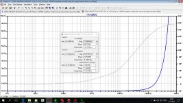
I am not sure if second question was for me, but here is output impedance (simulated), no difference with and without output inductor. I use low inductance, just 0.5 uH paralleled with 2.2 ohm. SR is more than 400V/usec.
By the way, the real THD is just 4 to 5 times higher than simulated one.
Attachments
Last edited:
BTW -- seems many here were unaware of thd in speakers.
A typical observation, we have all been aware for years (Paul Klipsch vs Bose for instance) just don't put it up there with a lot of other issues.
Richard, this looks like a very 'finished' amplifier. Yes, there can be a difference between 8 and 4ohm or lower loading that is really important, OR it can be just what is expected from just loading differences.
Earlier this year, I rejected a Parasound prototype, because it had such a problem. I had to insist on adding more output devices to fix it. It was most probably extra non-linear (for me) output impedance that caused this problem. I still don't exactly what went wrong.
Earlier this year, I rejected a Parasound prototype, because it had such a problem. I had to insist on adding more output devices to fix it. It was most probably extra non-linear (for me) output impedance that caused this problem. I still don't exactly what went wrong.
A typical observation, we have all been aware for years (Paul Klipsch vs Bose for instance) just don't put it up there with a lot of other issues.
Oh. Right. The typically, very high audible distortion levels we all know about.
But, for all practical purposes, ignore, in our quest for higher accuracy? .
-RNM
Last edited:
Richard, this looks like a very 'finished' amplifier. Yes, there can be a difference between 8 and 4ohm or lower loading that is really important, OR it can be just what is expected from just loading differences.
Earlier this year, I rejected a Parasound prototype, because it had such a problem. I had to insist on adding more output devices to fix it. It was most probably extra non-linear (for me) output impedance that caused this problem. I still don't exactly what went wrong.
Hi John. I am back in Calif now. Yes, it seems close to getting done. We had reliability issues to work out; new pcb. All is good now. Were your OPS devices mosfet or bipolar? I will be getting a complete set of measurements to be sent to me and shown here. Though high SR, it is rock stable.
I'll call you soon. I am freed up now and we can work on our own project again. Still, jet-lagged.
-Richard
Last edited:
Oh. Right. The typically, very high audible distortion levels we all know about.
But, for all practical purposes, ignore, in our quest for higher accuracy? .
You're entitled to your opinion. My quest is to preserve a cultural heritage of music that I enjoy. The quality of reproduction is WAY down on the chart. I could listen to old blues/cajun 78's all night long and never think of "accuracy".YouTube
Last edited:
here's some more Opinion...... the 4 Ohm at 1Khz is little changed from 8 ohm.
I'll do at other freq and 2 Ohm, later.
View attachment Test-result-v1.3.1-PCB-NO.-2-with-4-Ohm-load.pdf
THx-RNMarsh
http://eboutique.ric-vintage-records-shop.com/en_GB
I'll do at other freq and 2 Ohm, later.
View attachment Test-result-v1.3.1-PCB-NO.-2-with-4-Ohm-load.pdf
THx-RNMarsh
http://eboutique.ric-vintage-records-shop.com/en_GB
Last edited:
A typical observation, we have all been aware for years (Paul Klipsch vs Bose for instance) just don't put it up there with a lot of other issues.
Audio Musings by Sean Olive: The Science and Marketing of Sound Quality
-RM
These were also in my AES presentation. But to be precise gullwing thermal anomalies are different from crossover and need to be treated separately.
Scott, I was thinking of the gull wings that showed gain versus input level.
I don't think I saw your AES presentation, which one was that? I have access to the AES library.
Also see that PMA has made a distinction.
Jan
but here is output impedance (simulated),
This does not reflect output impedance non-linearity. It is just OL output impedance divided by feedback factor, no level dependence shown.
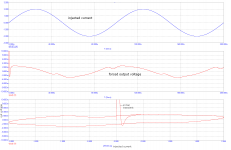
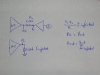
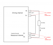
In case you are interested not only in nice plots, but also in something more useful, put the voltage generator not to the input, but to the output, via say 5 or 10 ohm resistor. Inject sine current of 1 - 10A into the output, measure current injected to the output and voltage at the output terminals of the tested amplifier. You can also make an X-Y plot of output voltage vs. injected current. Make this at several frequencies and then you will see output impedance nonlinearity.
Attachments
Like this Pavel? (same as Ed suggested?)
George
Sure. Test scheme attached, I have been using this method for about 10 years.
Attachments
Your link supports Scott's argument not your own. In fact Dr. Olive states ' The only pertinent information not shown in this graph is how loud the loudspeaker will play before producing audible distortion (trust me, this loudspeaker will play very loud! )' .
So Like Geddes Olive sees speaker distortion as a secondary issue at best.

You use the 2 channels of a single stereo amplifier ?Sure. Test scheme attached, I have been using this method for about 10 years.
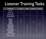
Sean Olive talks about distortions and other attributes that JBL trains its trained listeners to identify here: Audio Musings by Sean Olive: How to Listen: A Course on How to Critically Evaluate the Quality of Recorded and Reproduced Sound
For anyone interested, its possible to try out the training with a downloadable version of the software: http://harmanhowtolisten.blogspot.com/2011/01/welcome-to-how-to-listen.html
A copy of one of the figures is attached below.
For anyone interested, its possible to try out the training with a downloadable version of the software: http://harmanhowtolisten.blogspot.com/2011/01/welcome-to-how-to-listen.html
A copy of one of the figures is attached below.
Attachments
Last edited:
You use the 2 channels of a single stereo amplifier ?
Yes in case of dual mono amplifier with separate power supplies. Both channels are independent then.
- Status
- Not open for further replies.
- Home
- Member Areas
- The Lounge
- John Curl's Blowtorch preamplifier part II