Thanks.I was looking at the colored squares which seem to indicate a 10:1 variation.
And yes they say the cold regions are the 'bond attach shadows'.
I'll send yo the paper by mail - has a very nice thermal Spice model developed.
Jan
Ok, if I look really carefully, the very corner point does seem down at the 50 range.
But mosfets are generally surrounded by a guard ring structure. The dissipation stops 3 to 5 die thicknesses away from the saw edge, so measurement of the edge and particularly corners is meaningless, they are significantly distant from a 45 degree thermal transfer cone. The guard ring structure is also no dissipation, but merely there to support the voltage rating of the device.
That said, that is one heck of a robust die to even survive those temperatures. They must have bonded it by scrubbing it using either gold/germanium or gold/silicon, eutectic soft solders can't handle that kind of temperature. Even aluminum top metallization, 660 C melt, man that is really close. How the bond wires even held....
John
Last edited:
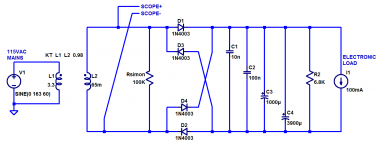
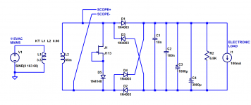
I got enthusiastic about the idea Ed Simon proposed in #91094 so I tried it out this morning. He suggests ripping out the snubber and replacing it with a simple resistor, straight across the secondary, chosen such that the resistor current is 10% of the load current. I reconfigured my test board to do just that; the schematic is shown in image1 below.
I decided to run the tests with 100mA of DC load, using an AC wall wart rated for 500mA AC RMS current. I figured: knock off a factor of two because their ratings are probably optimistic lies, and knock off another factor of 2.5 because my load draws from very well-filtered DC whereas the transformer current rating is AC. Thus I draw 100mA DC from a 500mA AC transformer.
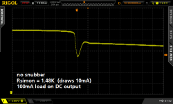
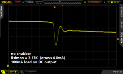
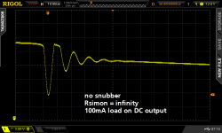
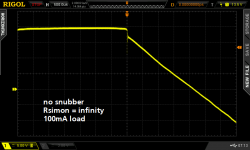
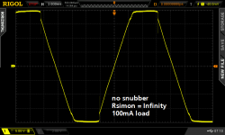
Images 2, 3, and 4 show the voltage across the secondary with "Rsimon" removed from its socket, at increasingly greater horizontal magnification. This is the ringing we hope to eradicate.
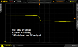
Image 5 shows what happens when you install a full CRC snubber, whose component values have been pre-tested on a bellringer jig. Ringing is completely annihilated.
Images 6, 7, 8 show the voltage across the secondary with the CRC snubber ripped out and thrown away, but with Rsimon added across the secondary. As hypothesized in post #90194, this simple stunt did indeed damp out most of the ringing. It's not quite as pristine and smooth as image 5 but it's a damn sight better than what you get when you do nothing at all (image 4). The resistor Rsimon does dissipate significant power: 72mW in image 6, 152mW in image 7, and 300mW in image 8. Whereas the CRC snubber dissipates negligible power.
But one component is certainly smaller and cheaper than three components. It also eliminates any concerns about "which capacitor type will give the best sound in my snubber" since it eliminates both capacitors! If you can tolerate the power dissipation, and if you don't mind the (slight) overshoot in the waveform, then maybe a 1R snubber might be an acceptable replacement for a 1R+2C snubber. Woo hoo.
_
I decided to run the tests with 100mA of DC load, using an AC wall wart rated for 500mA AC RMS current. I figured: knock off a factor of two because their ratings are probably optimistic lies, and knock off another factor of 2.5 because my load draws from very well-filtered DC whereas the transformer current rating is AC. Thus I draw 100mA DC from a 500mA AC transformer.
Images 2, 3, and 4 show the voltage across the secondary with "Rsimon" removed from its socket, at increasingly greater horizontal magnification. This is the ringing we hope to eradicate.
Image 5 shows what happens when you install a full CRC snubber, whose component values have been pre-tested on a bellringer jig. Ringing is completely annihilated.
Images 6, 7, 8 show the voltage across the secondary with the CRC snubber ripped out and thrown away, but with Rsimon added across the secondary. As hypothesized in post #90194, this simple stunt did indeed damp out most of the ringing. It's not quite as pristine and smooth as image 5 but it's a damn sight better than what you get when you do nothing at all (image 4). The resistor Rsimon does dissipate significant power: 72mW in image 6, 152mW in image 7, and 300mW in image 8. Whereas the CRC snubber dissipates negligible power.
But one component is certainly smaller and cheaper than three components. It also eliminates any concerns about "which capacitor type will give the best sound in my snubber" since it eliminates both capacitors! If you can tolerate the power dissipation, and if you don't mind the (slight) overshoot in the waveform, then maybe a 1R snubber might be an acceptable replacement for a 1R+2C snubber. Woo hoo.
_
Attachments

Thanks.
Ok, if I look really carefully, the very corner point does seem down at the 50 range.
But mosfets are generally surrounded by a guard ring structure. The dissipation stops 3 to 5 die thicknesses away from the saw edge, so measurement of the edge and particularly corners is meaningless, they are significantly distant from a 45 degree thermal transfer cone. The guard ring structure is also no dissipation, but merely there to support the voltage rating of the device.
That said, that is one heck of a robust die to even survive those temperatures. They must have bonded it by scrubbing it using either gold/germanium or gold/silicon, eutectic soft solders can't handle that kind of temperature. Even aluminum top metallization, 660 C melt, man that is really close. How the bond wires even held....
John
Those are getting up towards temperatures I used to use to anneal/create silicide contacts. Seriously gnarly stuff.
A (very) short digression: we talked a few pages back about current hogging due to temp differences on a MOSFET die. See attached - I thought this was a nice picture which I didn't want you guys to deprive off!
A 10:1 difference in T in degree centigrade across the die!
Courtesy an Infineon paper unearthed by my friend Ian Hegglun.
Jan
It seems that the German Fraunhofer Institute has done that studie together with Infineon (see the linked pdf).
http://www.iisb.fraunhofer.de/conte...ds/Publications/Therm_Modelling_2000_IISB.pdf
It seems that the German Fraunhofer Institute has done that studie together with Infineon (see the linked pdf).
http://www.iisb.fraunhofer.de/conte...ds/Publications/Therm_Modelling_2000_IISB.pdf
Ah, thanks for the link.
Pretty much a rehash of what I wrote in LA 9, but they used big words....

Seriously, nice work..
I see what that thermal graph was now, it's a thermal analysis run, not an actual scan. But it is a really good model, as they have included the thermal capacity of the aluminum bonding wires and run the simulation from start to about 1.1 milliseconds.. Whoa, very well considered. Even to the point that they angle the bonding wires exactly as they would be in the TO package, and included the heat capacity of the gate bonding wire.
I'd put the source wires at 20 to 25 mils each, the gate at 5 mils.
That paper is major good.
ps..because it is a high speed transient model, it isn't really needed to consider the die bond material, the base of the chip won't reach 230's C in a millisecond.
John
I don't think so. I think the reason why "Rsimon" reduces ringing is: plain old damping. It's the R in an RLC parallel resonant circuit and the smaller the R the higher the damping.I think the significance of the turn off ringing is voltage dominant is that the transformer secondary is abruptly unloaded.
I thought of a way to test this. Let's make sure the transformer secondary is not abruptly unloaded, and let's do this without introducing a parallel R. Instead let's introduce a parallel current source. See schematic in image 1.
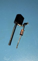
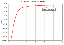
I put some J113 JFETs on a curve tracer and selected one whose IDSS was 17 milliamps. Then I soldered a diode in series with it to avoid forward biasing the JFET's gate-to-source junction when the transformer AC signal reverses. Photo of my merde-rig in image 2. When I curve trace this 2-component blob I get the I-V curve in image 3. It's a pretty decent approximation of a current source and the ringing happens when the voltage is 20 volts, see #91102.
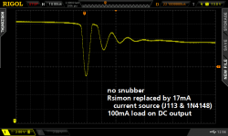
What do you know, this not-unloaded transformer secondary rings like a bell! See image 4 below. Even though there is a constant 17mA flowing in the secondary, when the 1N4003 rectifier diodes shut off, their not-soft recovery current pulse whacks the resonant circuit and it rings like a bell.
_
Attachments
Last edited:
Mark,
Cool. But a stage further than what I thought I meant. The transformer secondary being only loaded by stray capacitance and powered by energy stored in an inductor will try to go to infinite voltage constrained only by the resonance limit of the capacitor. So I expected the current into a resistor would limit the maximum voltage swing.
Also the other area where I was unclear was I expected the damping resistor to draw 10% of the transformer's AC current rating. Not compared to the load! But then you went above and beyond that. One small trick to the single resistor damping is you can use the pilot light for that! So it becomes essentially free.
It seems that the German Fraunhofer Institute has done that studie together with Infineon (see the linked pdf).
http://www.iisb.fraunhofer.de/conte...ds/Publications/Therm_Modelling_2000_IISB.pdf
It's really bad that the first thing I notices was that this paper was prepared in MS Word. Having just submitted/edited a journal paper of my own, I can confess it's *terrible* to do layout in.
A (very) short digression: we talked a few pages back about current hogging due to temp differences on a MOSFET die. See attached - I thought this was a nice picture which I didn't want you guys to deprive off!
A 10:1 difference in T in degree centigrade across the die!
Courtesy an Infineon paper unearthed by my friend Ian Hegglun.
Jan
That die is probably in heavy avalanche and the result are hot spots which almost always lead to chip failure.
When I was involved in that business about 15 years ago, we hired a PhD grad (Adrian Koh - you can google to see his paper) to investigate the issue more fully. Customers wanted a clear handle on how to rate the devices - it was still pretty hit and miss up until then - and they wanted the smaller, cheaper die (nothing changes) that Trench technology offered.
Most professional applications today that use mosfets to switch an inductive load do not use catch diodes or snubbers - the devices are selected to handle the full inductive energy dump and not suffer from any degradation or 'hots potting' due to repetitive inductive energy dump. Example applications: ABS systems, fuel injector solenoids.
Mark- What is the self resonant frequency of the transformer secondary? The transformer is much more than a big inductor. How much of the ringing goes back to the primary? That can be hard to measure, With a low source impedance (depending on the power its connected to) the ringing may only be visible on the current waveform.
we hired a PhD grad (Adrian Koh - you can google to see his paper)
That must be the guy who currently runs NXP in the US?
Jan
Demian,
Have you ever measured the frequency response of a power transformer?
I have seen unloaded EI over under types -3dB at 80 KHz unloaded when driven from a low source impedance and flat packs roll off at 6 KHz.
The ringing shown in 91051 was 96 KHz ish. Never measured a wall wart but they usually are a special inefficient EI over under from the ones I have opened up.
Last edited:
That must be the guy who currently runs NXP in the US?
Jan
No - he's a Business Dev guy in the Auto Division
https://www.linkedin.com/in/adriankoh
The paper plus some others are linked in his profile.
Yah see, clever PhD guys make very good marketers . . .
I don't know and don't have the equipment to measure. How about if I order one of these extremely similar transformers and send it to you? Would you be able to make those measurements and answer those questions? If so then you could make the measurements, answer the questions, and then send the trafo over to me. I would hook it up to my test board and observe the ringing with and without full CRC snubber, minimalist single-R snubber, etc.Mark- What is the self resonant frequency of the transformer secondary? The transformer is much more than a big inductor. How much of the ringing goes back to the primary? That can be hard to measure, With a low source impedance (depending on the power its connected to) the ringing may only be visible on the current waveform.
Demian,
Have you ever measured the frequency response of a power transformer?
I have seen unloaded EI over under types -3dB at 80 KHz unloaded when driven from a low source impedance and flat packs roll off at 6 KHz.
The ringing shown in 91051 was 96 KHz ish. Never measured a wall wart but they usually are a special inefficient EI over under from the ones I have opened up.
The response (thru) is one issue. The parasitic capacitance vs inductance at the output side is separate and also can react with the rapid change in current from a rectifier. I think the next step would be a good model of the transformer that would account for the parasitics. Its conceivable that an impedance protected transformer would be lower in resonant q than a higher current transformer.
I don't know and don't have the equipment to measure. How about if I order one of these extremely similar transformers and send it to you? Would you be able to make those measurements and answer those questions? If so then you could make the measurements, answer the questions, and then send the trafo over to me. I would hook it up to my test board and observe the ringing with and without full CRC snubber, minimalist single-R snubber, etc.
I have a few like that in my junk box. I'll try to measure one in the next few days and send it on to you.
Perhaps the design features which make the transformer able to tolerate output short circuits without catching fire, lead to higher damping and lower Q. On the other hand, the low cost construction and the 6 foot long piece of two conductor zip cord on the secondary, typically give quite large values of large leakage inductance. Often 1000X higher than the leakage inductance of a 400VA toroid from Antek. Huge L_leakage means the "characteristic impedance" of the secondary's parallel RLC network (=sqrt(L/C)) is quite high, so a low-energy stimulus can provoke ringing very easily.Its conceivable that an impedance protected transformer would be lower in resonant q than a higher current transformer.
A couple a three years ago I hooked up a rectifier+capacitor+loadresistor test board {not the present one} to several dozen different transformers, looking for the transformer that gave the tallest ringing amplitude (Vring/Vsecondary) with the least damping / most cycles of oscillation. I tried split bobbin EI cores, toroids, conventional EI cores, R cores, low profile PC mount, wall warts, ad nauseum. The "winner", the ring-a-ding-dingest most oscillatory transformer of all, was a 24VAC wall wart rated for 1 ampere. FWIW.
R-core transformers ring. More than toroids, less than wall-warts.
If you send me an R-core transformer and a "control" transformer (EI?? Toroid??), I'll connect each of them to the exact same test board and test each of them under the exact same conditions. Then I'll post the results here. Any differences in the ringing will be due to differences between the transformers, and nothing else.
I'm in California USA so international shipping rates will apply.
- Status
- Not open for further replies.
- Home
- Member Areas
- The Lounge
- John Curl's Blowtorch preamplifier part II