Probably.Ummm, No DBLTs so therefore your opinion of this amp is invalid ?.
") But I do have an opinion, none the less. Was just curious if anyone else has used an amp with similar spectra and formed an opinion. There has been a good bit of discussion of correlating subjective impression with measurements.
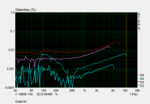
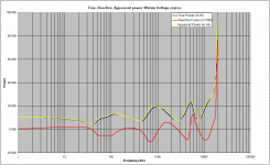
But I do have an opinion, none the less. Was just curious if anyone else has used an amp with similar spectra and formed an opinion. There has been a good bit of discussion of correlating subjective impression with measurements.Yes, I noticed that. Wonder if I can hear it? The harmonic distortion is strongly odd order, but does decrease in amplitude as the order increases. Another plot (below) shows that distortion rises with frequency. I don't know what the big H2 bump down low is, unless it's picking up 120 & 180 Hz mains noise.The intermod is higher than the amps I have in house, though interestingly, on the 11-12, it manifests as sidebands rather than a first order peak at 1k.
Source impedance is 300 ohms, balanced. Amp input impedance is 20K balanced. Input attenuation is about 10dB thru the built in volume knobs.What does source impedance look like?
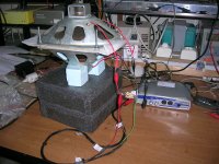
This is a Class-H amp with a heavy toroid transformer.
Attachments
Yes, and I find that effect is lasting for days.
Dan.
You do realise he was trolling you there. The RF parts were in the trunk. Any heat was just from the insulation of the headset onto his sweaty head.
No sh*t fact of the day. Power amplifiers in phones are way off 100%. so the phone gets warm during a call. The whole end to end is maybe 10% efficient. So hold a phone to your head whilst on a call and things will get warm. But nothing to do with the heating effect of non-ionising radiation.
Even if a cell phone would heat up part of one's brain a few degrees, a simple flu can bump up cerebral temperature by close to 10.
I've evaporated more cells with barrels of hard liquor.
Yeah, nowhere near a degree anyhow. And there are plenty of confounding natural factors that would be in a similar (or much greater) range. I don't know if there are cellular structures that are uniquely suited for absorption of common cell frequencies (collagen?), which would put much more stress on any one structure versus hyperthermia.
As to the latter, I'm sure.
Thanks George.The same signal and amplifier was feeding both drivers in the physical arrangements and electrical connections I described.
I was measuring the impedance of the circuit i.e. of the two drivers.
Configurations IIIa1) and IIIb1) zero out the motional impedance on both drivers due to strong acoustically coupling (see attachment), being out of face acoustically.
My concern is with the V/I space only. The acoustic mass/resonator system reactance above and below resonance is where the biggest problem lies AFAIK.
As to the bounds of the V/I space, the vc resistance does not necessarily define that. The model needs to include the energy return mechanism, which is through the inductor only..
For example, model a speaker as a 1 ohm resistor and a 1 henry transformer primary (1 to 1). With a signal drive into the system, say 1 hz, it's easy to calculate the current vs time.
Now, attach a source to the secondary, say 1 volt to simulate energy return due to reactive storage. In one phase, it subtracts from the source voltage such that the current draw is less (as in resonating), and opposing phase causes higher current draw. So it is easy to double the current using the return energy. The question is always, what level of effect will the acoustic mechanism provide.
I am not concerned with whether or not the current exceeds that which the DCR would indicate. I am quite concerned with the amp topology and it's ability to control the output when Q2 and 4 are involved.
John
Yes, no scientific studies correlating cell phones and cancer.
As I recall, one a while back demonstrated a correlation, with more cancers on the side of the brain the phone was on.
I also recall the study had 99 subjects, 50 with caner on the phone side, 49 on the opposite.
Yet this result was touted as significant.
On must always be concerned with the "needs more study" conclusion, especially if it is stated by the people who earn a living doing the study.
I take it all with a grain of salt...
John
Yet this result was touted as significant.
In the same way that camera phones have done it in for bigfoot ( https://xkcd.com/1235/ ) one would have thought that enough metadata was out there now to find statistical significance if it existed. Not that this type of stats is something I can do so I may be missing something obvious. But when you have several billion users...
Well this solves half the problem, now where can I get aluminum foil hats?
These Glasses Block Your Phone's Blue Light to Improve Sleep | Digital Trends
These Glasses Block Your Phone's Blue Light to Improve Sleep | Digital Trends
I hope they are taking people for a ride, but suspect not!
this lot are defiantly serious https://wirelessarmour.co.uk/
EDIT: Spent 12 years working on GSM basestations. I have 5 kids. My boss, the head of RF design has 9. On sample of 2 RF makes you MORE fertile
this lot are defiantly serious https://wirelessarmour.co.uk/
EDIT: Spent 12 years working on GSM basestations. I have 5 kids. My boss, the head of RF design has 9. On sample of 2 RF makes you MORE fertile
Thanks George.
My concern is with the V/I space only. The acoustic mass/resonator system reactance above and below resonance is where the biggest problem lies AFAIK.
As to the bounds of the V/I space, the vc resistance does not necessarily define that. The model needs to include the energy return mechanism, which is through the inductor only..
For example, model a speaker as a 1 ohm resistor and a 1 henry transformer primary (1 to 1). With a signal drive into the system, say 1 hz, it's easy to calculate the current vs time.
Now, attach a source to the secondary, say 1 volt to simulate energy return due to reactive storage. In one phase, it subtracts from the source voltage such that the current draw is less (as in resonating), and opposing phase causes higher current draw. So it is easy to double the current using the return energy. The question is always, what level of effect will the acoustic mechanism provide.
I am not concerned with whether or not the current exceeds that which the DCR would indicate. I am quite concerned with the amp topology and it's ability to control the output when Q2 and 4 are involved.
John
Common problems unite people
I am fiddling with the same issues. I agree with what you say in the two first paragraphs.
I will try to work the problem on a cycle base as you suggest
I attach results of power calculations, based on the data from impedance scans of the two elliptical drives.
The curve of reactive power shows the frequencies where power is consumed by the load (area where curve takes positive values) and the frequencies where power is returned to the source (area where curve takes negative values).
Does this returned power causes problems to amplifiers and how?
George
Attachments
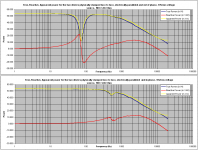
Red has the same profile as a phase response. On either side of the resonant point, power is send to and returned from the load, but the red above/below zero indicates when the return power is delivered, either before or after the drive signal.Common problems unite people
I am fiddling with the same issues. I agree with what you say in the two first paragraphs.
I will try to work the problem on a cycle base as you suggest
I attach results of power calculations, based on the data from impedance scans of the two elliptical drives.
The curve of reactive power shows the frequencies where power is consumed by the load (area where curve takes positive values) and the frequencies where power is returned to the source (area where curve takes negative values).
Does this returned power causes problems to amplifiers and how?
George
My HP LCR meter does the same thing btw, when I'm in Ls/Rs mode. It will read positive inductive above resonance, and negative inductance below. It is being forced to look for inductance reactance, and a capacitive reactance makes it think there is negative inductance.
John
It seems to me that a PA would need to handle the current of just the voice coil R and not the min sine wave average Z value. For a pulse or step response, the current is max at t=0 which will be that which only the R limits to.
Richards
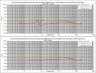
For a single driver with a benign impedance curve and no passive cross over in between, yes, the highest current demand is governed by coil resistance at very low frequencies. The inductive reactance of the coil which increases with frequency, reduces current flow progressively as frequency increases. See diagrams on my previous post # 79195).
However, this may not be the case when passive cross over elements are present.
See attached diagrams referring to a three way loudspeaker (*). Details for this loudspeaker are in posts # 78872 and #78903
http://www.diyaudio.com/forums/loun...ch-preamplifier-part-ii-7888.html#post4639290
http://www.diyaudio.com/forums/loun...ch-preamplifier-part-ii-7891.html#post4639978
George
(*) Ed , there is a real issue with the tweeter branch
Attachments
Last edited:
The inductive reactance of the coil which increases with frequency, reduces current flow progressively as frequency increases.
That occurs from 700 hz up in that plot.
From 20 to 200, you are seeing the energy storage mechanism of the air and the moving element mass with spider. The meter is interpreting that as either positive or negative storage.
John
- Status
- Not open for further replies.
- Home
- Member Areas
- The Lounge
- John Curl's Blowtorch preamplifier part II