Many here, who use their ears, and trust their personal judgements often come up with what really works, and what sort of works, you might say. Class D amps have always been problematic with me, for example, except to bass, (maybe). Others have heard the same thing. At the moment I am working on a Class D amp, so any input from you all would be appreciated. No, not the digital, just the analog part, but I am now focusing on Class D as a design. Thanks in advance. Hear no difference people, need not apply. '-)
http://www.diyaudio.com/forums/power-supplies/193705-switcher-emc-design.html
I have always hated Ferrite beads, based on early experience with them in the early 70's. I could not measure much then, but I just did NOT like the overall sound effect. This paper might be an eye opener.
Would you use a 70s computer.... things move on!
Reduce EMI In Your Class D Amplifiers | Analog content from Electronic Design
https://www.maximintegrated.com/en/app-notes/index.mvp/id/3973
https://www.maximintegrated.com/en/app-notes/index.mvp/id/5342
Results of five second searching.
IMO, radiated RF is the subjective Class D killer.
Some individuals are sensitive to local sources of EMR....not so much the level as the 'nature' or spectrum of the magnetic disturbance.
The are ways of rendering this EMR innocuous ime.
Dan.
Sorry but if your class D is radiating rf then it a crap design... A class D amp is a modulated SMPS they can both be done so they don't radiate, CE and FCC get a bit tetchy about products that radiate...
That's where measurement comes in useful as well as good engineering practice...... And a basic understanding of rf and noise coupling mechanisms....

I used to do warranty service on HK and my experience back then was 2RU or so high late 80's gold fronted integrated amps...I forget the model numbers.
I found their sound to be 'drive me out of the room' falsely 'sharp and detailed', and their typical failure mode of cracked solder joints due to high running temps did not endear me to them.
That said, I had a friend with an old school HK preamp with 5 band eq on the front panel driving HK Citation 16.
This combination running into chest high JBL's (I forget the model, L220 ?) did a wonderful job at a bunch of parties, with huge fat sound and dancin' on the tables all night until the sun came up.
I have found/developed an interesting filter solution that makes anything sound good/pleasing/detailed/musical, so nowadays I just don't bother to get anal about any of this any more.
Dan.
I found their sound to be 'drive me out of the room' falsely 'sharp and detailed', and their typical failure mode of cracked solder joints due to high running temps did not endear me to them.
That said, I had a friend with an old school HK preamp with 5 band eq on the front panel driving HK Citation 16.
This combination running into chest high JBL's (I forget the model, L220 ?) did a wonderful job at a bunch of parties, with huge fat sound and dancin' on the tables all night until the sun came up
.I have found/developed an interesting filter solution that makes anything sound good/pleasing/detailed/musical, so nowadays I just don't bother to get anal about any of this any more.
Dan.
Last edited:
Sure.Sorry but if your class D is radiating rf then it a crap design... A class D amp is a modulated SMPS they can both be done so they don't radiate, CE and FCC get a bit tetchy about products that radiate...
That's where measurement comes in useful as well as good engineering practice...... And a basic understanding of rf and noise coupling mechanisms....
Is IcePower in the category of crap re radiated RF ?.
Dan.
Last edited:
Do they radiate rf? if so then there is something wrong. Most competent designs are done so they DONT radiate rf that's what EMC testing is for. As for IcePower don't have any of their stuff so cant comment on radiated rf.
Rayma posted a good link RE: Bruno Putzy AES presentation regarding EMI, I started a thread 2011 on switcher EMC design (didn't go far, around that time someone on another thread said this is DIY, EMC doesn't matter, so I gave up), there is a ton of info regarding good practice, especially layout out there.
Those that dis ferrites, which type of ferrite specifically should we be wary of in audio?
Thanks a lot, that's just given me a week of study.........all good.
Dan.
Sure.Do they radiate rf? if so then there is something wrong. Most competent designs are done so they DON'T radiate rf that's what EMC testing is for. As for IcePower don't have any of their stuff so cant comment on radiated rf.
I don't have figures re IcePower, so I can't comment, except to say that ime I feel/know when they are powered/idling, ditto the Sony mixer-amp I mentioned.
Typical ferrites contain Manganese and Nickel, and these elements in direct contact/intake can be toxic.Rayma posted a good link RE: Bruno Putzy AES presentation regarding EMI, I started a thread 2011 on switcher EMC design (didn't go far, around that time someone on another thread said this is DIY, EMC doesn't matter, so I gave up), there is a ton of info regarding good practice, especially layout out there.
Those that dis ferrites, which type of ferrite specifically should we be wary of in audio?
I suspect/propose that Mg/Ni spectrum radiation can excite/enhance already present Mg/Ni in biological processes.
Dan.
You do realise this is horribly close to the studies on teachers who complained that the wifi gave them headaches? Kudos if you can hear 300kHz of courseSure.
I don't have figures re IcePower, so I can't comment, except to say that ime I feel/know when they are powered/idling, ditto the Sony mixer-amp I mentioned.
Typical ferrites contain Manganese and Nickel, and these elements in direct contact/intake can be toxic.
I suspect/propose that Mg/Ni spectrum radiation can excite/enhance already present Mg/Ni in biological processes.
Dan.
You'll be dangling crystals over your food next!
You'll be dangling crystals over your food next!
I regularly put crystals on my food, don't you? Or do Brits really only eat bland food?
He who laughs last, laughs longest.You do realise this is horribly close to the studies on teachers who complained that the wifi gave them headaches? Kudos if you can hear 300kHz of course
You'll be dangling crystals over your food next!
Dan.
I suspect/propose that Mg/Ni spectrum radiation can excite/enhance already present Mg/Ni in biological processes.
Dan.
I think you might be getting a little out of your element here. NMR frequencies are somewhat higher that the audio band.
Thanks Scott, yes I do understand that.I think you might be getting a little out of your element here. NMR frequencies are somewhat higher that the audio band.
Dan.
I regularly put crystals on my food, don't you? Or do Brits really only eat bland food?
That and warm beer.
https://www.youtube.com/watch?v=vWkUbyjEsTY This may not transfer too well, but hilarious if you know anything about UK friday night habits.
He who laughs last, laughs longest.
Dan.
Dan, there's another interpretation of that old adage;
He who laughs last, is not being serious.
This discussion about the possibility for a single driver (no passive cross-over interfering) to show a Z lower than it’s DC resistance makes me scratch my head.
With the means I have and under the restrictions (if any) of sinusoidal continuous excitation, I tried to test the idea that an external force due to adverse acoustic loading may make the moving assy resist the action of the Lorenz force in an awkward way and reduce the Z of the coil below it’s RDC value.
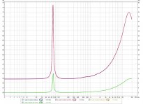
I took impedance plots from two bare drivers of the same type connected in all possible combinations on air (not boxed).
I) Each one single.
II) Both physically placed at a distance to each other to reduce acoustic coupling and electrically connected in series
IIa1) in phase and
IIa2) out of phase.
Then electrically connected in parallel
IIb1) in phase and
IIb2) out of phase.
III) Both physically placed face to face, clamped against each other to maximise acoustical coupling and electrically connected in series
IIIa1) in phase and
IIIa2) out of phase.
Then electrically connected in parallel
IIIb1) in phase and
IIIb2) out of phase.
DC resistance as measured with a Keithley 175 bench multimeter is
1st driver: 3.53 Ohm
2nd driver: 3.84 Ohm
Drivers in series: 7.4 Ohm
Drivers in parallel: 1.86 Ohm
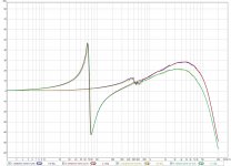
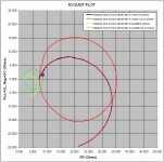
By looking at the impedance plots, there is no case which shows an impedance lower than the DCR of the respective electrical connection.
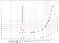
Arrangement III (speakers face to face, clamped against each other) presents a strong acoustic coupling of the cones.
When coils are electrically connected in phase, cones are moving in opposite directions and so acoustic loading hinders cone movement, thus no impedance peak at resonance.
The motional impedance at resonance is nullified, the Z drops down to the DCR value.
George
With the means I have and under the restrictions (if any) of sinusoidal continuous excitation, I tried to test the idea that an external force due to adverse acoustic loading may make the moving assy resist the action of the Lorenz force in an awkward way and reduce the Z of the coil below it’s RDC value.
I took impedance plots from two bare drivers of the same type connected in all possible combinations on air (not boxed).
I) Each one single.
II) Both physically placed at a distance to each other to reduce acoustic coupling and electrically connected in series
IIa1) in phase and
IIa2) out of phase.
Then electrically connected in parallel
IIb1) in phase and
IIb2) out of phase.
III) Both physically placed face to face, clamped against each other to maximise acoustical coupling and electrically connected in series
IIIa1) in phase and
IIIa2) out of phase.
Then electrically connected in parallel
IIIb1) in phase and
IIIb2) out of phase.
DC resistance as measured with a Keithley 175 bench multimeter is
1st driver: 3.53 Ohm
2nd driver: 3.84 Ohm
Drivers in series: 7.4 Ohm
Drivers in parallel: 1.86 Ohm
By looking at the impedance plots, there is no case which shows an impedance lower than the DCR of the respective electrical connection.
Arrangement III (speakers face to face, clamped against each other) presents a strong acoustic coupling of the cones.
When coils are electrically connected in phase, cones are moving in opposite directions and so acoustic loading hinders cone movement, thus no impedance peak at resonance.
The motional impedance at resonance is nullified, the Z drops down to the DCR value.
George
Attachments
-
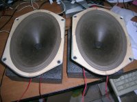 1 the two elliptical speakers.JPG663.9 KB · Views: 174
 -
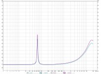 2 single drivers impedance.jpg190.6 KB · Views: 164
 -
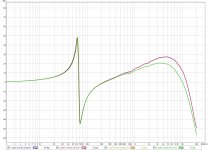
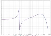 3 single drivers phase.jpg173.1 KB · Views: 162
 -
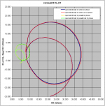
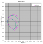 4 single drivers Nyquist.PNG28.4 KB · Views: 160
 -
 5 open impedance.jpg206.8 KB · Views: 138
 -
 6 open phase.jpg192.6 KB · Views: 29
 -
 7 open Nyquist.PNG34.3 KB · Views: 36
 -
 8 clamped face to face impedance.jpg208.7 KB · Views: 41
 -
 9 clamped face to face phase.jpg197.6 KB · Views: 36
 -
 10 clamped face to face Nyquist.PNG32.9 KB · Views: 35
- Status
- Not open for further replies.
- Home
- Member Areas
- The Lounge
- John Curl's Blowtorch preamplifier part II