Actually it happens that I am lactose intolerant. No ice cream for me.
My condolences. There would go half my reason for existence.
felt so
Yikes, that ugh lack ho has only won bobble.
(It's no use to deny it any longer, I already did it 40 years ago, but not what you think it is. But maybe it is. Is it ?)
Lesnerize?Yikes, that ugh lack ho has only won bobble.
(It's no use to deny it any longer, I already did it 40 years ago, but not what you think it is. But maybe it is. Is it ?)
I will have a double-sided PCB with groundplane in a week, to avoid possible test board impedance and coupling issues. We shall see then, if anything is improved.
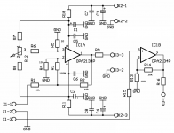
As I promised, I have prepared a double-sided PCB for the test of opamp susceptibility to EMI and repeated the test with LM4562, NE5532, OPA2134 and TL072. The susceptibility of BJT input opamps to EMI has been considerably reduced in this evaluation PCB board, but the relative order of results has remained the same. 4562 worst, JFET opamps best. If I put a finger on an IC package, noise spectrum and time record becomes the same as in the previous test at breadboard PCB. It shows that the effect has been induced and air-coupled.
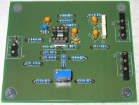
Attached is a schematic and photo of the new test board. Next post will show the measured results.
Attachments
I think part of the difference lie in the loop gain differences ang GBW products of these devices. The NE5532 LF Gain is spec'd at 100 000 (100 dB OLG), the OPA2134 at 120 dB while the 4562 is spec'd at 140 dB. In you config, any noise between the inverting input and the junction of the feedback resistors will be amplified 100 times more on the 4562 device. Clearly, it is going to be much more sensitive to layout.
We don't know the internals of this device, but clearly there are possibly other factors at play. The very low 'signal bias' currents may also be a factor on the 5532 which only has 20 dB loop gain in the test set-up.
Nevertheless, very interesting results and food for thought Pavel - thank you for sharing.
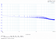
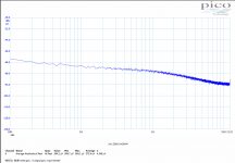
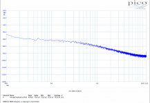
New results for 4562, 5532 and 2134. (noise gain 86dB, signal gain -1x, input shorted)
The susceptability to HF is clear on these devices. Also, they are for very small/compact circuitry -- mostly inside the small IC. Discrete amps.... pre and power would be a lot more susceptible with its circuitry spread out over a large area.
THx-RNMarsh
Strange how all English native speakers use word complimentary instead complementary. Completely different meaning.
'All'. That's a bit of a generalisation
") I've found no problem with spell checkers either
I've found no problem with spell checkers either No two grammar checkers can agree on a proper sentence structure.
So neither could those that programmed them
Lesnerize?
I got a demo of a 7-axis robot arm yesterday, cnc'd a copy of a 3D scanned upper leg stump for fitting of a prosthesis, Vorum Canfit software (Vancouver company, if the company name wasn't a giveaway)
For laughs, and making me wet, the main frame had a 700G file of an aircraft carrier. Now that was Lesnerizing.
(slang joking with my sisters long before I turned ten in English/American, German, French and Spanish. My oldest sister still is totally into Spain, currently on the lookout for a 24/7 crib there. The 2nd studied French and English, the 3d never got beyond the Sex Pistols and lesquit drugs)
Last edited:
We don't know the internals of this device, but clearly there are possibly other factors at play. The very low 'signal bias' currents may also be a factor on the 5532 which only has 20 dB loop gain in the test set-up.
Nevertheless, very interesting results and food for thought Pavel - thank you for sharing.
It's definitely interesting and leaves me wondering the mechanism.
But I'd also like to redouble the thanks to Pavel for the tests and hope (selfishly) that we get some more opamps through here.
I have a question regarding opamp implementation
Recently I tried to find the best opamp and circuit using listening comparison.
5532 was out very early in the competition, but 4562 stayed to the "final". I don't like the sound of 4562 because it sounds nervous and makes me cannot enjoy the music, but in terms of "hi-fi" I think it was on the top. So that's why I tried to find a proper implementation for the 4562, to see if I can enjoy it once I found the right implementation.
Later implementation might include shielding the opamp and the proper RC network on the FB path, but from the previous comparison, my preference or score for 4562 was higher when the gain was higher (I tried up to 10dB). My temporary conclusion was that I should use higher gain for the 4562 and then find a way to reduce it...
Simple solution is of course reducing the gain with resistors (voltage divider). I'm thinking about 8k2|2k2 or something...
So what do you think? Any solution to bring the gain down electronically/actively?
But I'd also like to redouble the thanks to Pavel for the tests and hope (selfishly) that we get some more opamps through here.
Recently I tried to find the best opamp and circuit using listening comparison.
5532 was out very early in the competition, but 4562 stayed to the "final". I don't like the sound of 4562 because it sounds nervous and makes me cannot enjoy the music, but in terms of "hi-fi" I think it was on the top. So that's why I tried to find a proper implementation for the 4562, to see if I can enjoy it once I found the right implementation.
Later implementation might include shielding the opamp and the proper RC network on the FB path, but from the previous comparison, my preference or score for 4562 was higher when the gain was higher (I tried up to 10dB). My temporary conclusion was that I should use higher gain for the 4562 and then find a way to reduce it...
Simple solution is of course reducing the gain with resistors (voltage divider). I'm thinking about 8k2|2k2 or something...
So what do you think? Any solution to bring the gain down electronically/actively?
Yep
Hi Jay,
Two things to note:
1) When the gain is higher, the feedback is lower. Take it to the extreme with zero feedback and the sound gets even better. Of course then the gain is too high....
2) As you note a feedback amp has an built-in design flaw. All RFI picked up on the output lead/cable/whatever is also coupled back to the input where it causes all kinds of trouble. Zero feedback designs have an output port that is just an output port and are less prone to these problems.
Just sayin'. YMMV.
Later implementation might include shielding the opamp and the proper RC network on the FB path, but from the previous comparison, my preference or score for 4562 was higher when the gain was higher
Hi Jay,
Two things to note:
1) When the gain is higher, the feedback is lower. Take it to the extreme with zero feedback and the sound gets even better. Of course then the gain is too high....
2) As you note a feedback amp has an built-in design flaw. All RFI picked up on the output lead/cable/whatever is also coupled back to the input where it causes all kinds of trouble. Zero feedback designs have an output port that is just an output port and are less prone to these problems.
Just sayin'. YMMV.
Any solution to bring the gain down electronically/actively?
Have you tried operating it at low voltage gain like you want, but increasing the noise gain instead?
Last edited:
Have you tried operating it at low voltage gain like you want, but increasing the noise gain instead?
No, I haven't gone that far. Do you have special tricks for that approach?
I didn't use many circuits. Not enough PCBs for that, but I planned to do more variations with single opamps comparison...
My "final" circuit was non-inverting, because I found that inverting circuit (which has lower voltage gain versus noise gain) needed input buffer, so more stages with inverting configuration, and I decided that it didn't sound better.
But okay, so I think I will focus on using non-inverting for 4562. I think it is more suitable for it. Unfortunately my PCB required the input buffer to be from the same dual opamp. So one 4562 for the input buffer and the gain stage. I planned to have different opamp for the buffer stage, my intention was LF353 for the buffer.
Last edited:
No, I haven't gone that far. Do you have special tricks for that approach?
For a noninverting amplifier circuit, the noise gain can be increased by adding a resistor directly
between the positive input and the negative input. I would start with a value about equal to the
resistor in the nfb network that goes to ground. For example, if you have a gain of 6, using
5k and 1k in the nfb, start with a 1k between the inputs. Then you can experiment with smaller values.
The added resistor is bootstrapped, and so doesn't cause a low input impedance.
Last edited:
For a noninverting amplifier circuit, the noise gain can be increased by adding a resistor directly
between the positive input and the negative input. I would start with a value about equal to the
resistor in the nfb network that goes to ground. For example, if you have a gain of 6 using
5k and 1k in the nfb, start with a 1k between the inputs. Then you can experiment and go smaller from there.
The added resistor is bootstrapped, and so doesn't cause a low input impedance.
Thank you very much! I will try that.
- Status
- Not open for further replies.
- Home
- Member Areas
- The Lounge
- John Curl's Blowtorch preamplifier part II