Source impedance needs defining, and what is meant by 'loss' in this context ?.Max that is actually a lot of variations to take into account. Considering all he gave originally was a piece of wire of a certain gauge folded upon itself. No distances besides the length of the wire and the gauge originally. You could make many variation right there. I don't think I would set up an experiment without some strong conditions that could be varied one at a time.
Ed has explained the experiment as measuring across the looped conductor (at the xlr connector) ie...
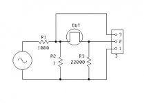
Run 5 mV through a 3' cable terminated with 20K. Look across the cable with a differential input complex FFT and see how the losses vary with frequency across the audio band. The voltage will be down in the dirt as the cable resistance is about .003 ohms. So if you use lots of samples and only look at .95 F to 1.05 F it should be possible to pick out the loss signal and phase.
The loss goes up with frequency. The inductance of the wire is less than 50 nH. At 20 kHz the reactance of the cable should be .007 ohms. The loss is greater than that. You can repeat the experiment with the same length of a thinner wire such as a single strand from a cat5 cable. The low frequency loss on my rig is higher but the high frequency loss is lower.
Dan.
This was my first circuit. I would suggest using 100 ohms instead of 1 ohm as that would be a better representation of an audio source. The IEC load spec's call for 20K or greater. 22K should work higher values will drop the signal we wish to look at.
Try the test with .005 volts into the cable under test. Try frequencies of 110, 316, 1100, 3160 & 11000 hertz. Use a 32,000 point or greater FFT average at least 128 runs and look at the frequency under test from .95 F to 1.05 F or even tighter .98 F to 1.02 F. Then repeat the test with .5 volts.
I would suggest using two cables one 10 gauge (5.26 mm sqd) and one 24 gauge (.2 mm sqd.)
The loss in the wire would be shown by the voltage across it. At .005 volts DC the voltage should be around .7 nV for the 10 gauge wire 3' long. It should rise to just above 1.1 nV at 11,000 hertz.
Then please let me know if you observe anything interesting.
Attachments
Last edited:
One remark: using the current source does make the voltage variation at the cascode sources due to the gate voltage divider noise much smaller. This will be true for both PS noise and resistor thermal noise. I was going to suggest bypassing of the uppermost R and lowermost R as well, although the thermal noise contribution is quite small....
My next questions would be :
1. While JFETs and MOSFETs are not perfect penthodes, the Id variation with Vds is still small.
So would adding 4 caps to the cascode gate voltage network not improve PSRR ? (See attached.)
2. If it does, is there any disadvantage of using C1~C4 ?
3. Why not go one step further and use current regulating diodes (JFET CCS) to replace R16, R19 ?
Patrick
.
For PSR with the original circuit, yes, the current regulating diodes pulling to common would help a lot.
I already did the thinner wire had less loss.
The thinner wire has less loss as a percentage of the toal change within audio freq range. IOW.... the loss is constant out to a higher freq. See N.Pass work.
Do you have access to a Network analyzer to measure the DUT Z vs Freq?
THx-RNMarsh
Last edited:
The thinner wire has less loss as a percentage of the toal change within audio freq range. IOW.... the loss is constant out to a higher freq. See N.Pass work.
Do you have access to a Network analyzer to measure the DUT Z vs Freq?
THx-RNMarsh
Actually the thinner wire had less total loss across most of the audio band. Not just percentage basis.
No network analyzer. I almost bought one but it was selling for $200 from someone who had never sold anything like it, so I though it was a fraud. Turns out it was real and sold for $200!
I can get the Z from the complex FFT
Last edited:
No network analyzer. I almost bought one but it was selling for $200 from someone who had never sold anything like it, so I though it was a fraud. Turns out it was real and sold for $200!
I can get the Z from the complex FFT
Hi Ed,
How big is the AC signal at 32K FFT and 96K sampling and depending on window applied there would be ~4 bins of noise or 2X? So trying to find a nV with a 1nV pre-amp would not yield to averaging only a HUGE FFT length.
I would suggest repeating the experiment with the wire straight....as well just for reference.
You can't measure the impedance of a straight wire.
Hi Ed,
How big is the AC signal at 32K FFT and 96K sampling and depending on window applied there would be ~4 bins of noise or 2X? So trying to find a nV with a 1nV pre-amp would not yield to averaging only a HUGE FFT length.
You are right I am not seeing 1 nV that is below the noise, what is interesting is where the signal is cleanly above the noise. The 24 gauge wire has 17 nVish at DC and that is just seen at 110 Hz.
The AP has a feature called optimum sampling rate for any given bandwidth. I usually use the maximum which is about 50K for my model.
I know, but you could provide a distant return path, ala some EMC tests, that pushes the magnetic coupling to the limits, it would be an interesting comparison to a closely coupled wire loop...
Figure 4 in the link gives a nice picture of proximity effect:
http://www.ultracad.com/articles/skin effect.pdf
Now I might be wrong here but I suspect that this is possibly a reason for the measured result...
Just a thought")
Figure 4 in the link gives a nice picture of proximity effect:
http://www.ultracad.com/articles/skin effect.pdf
Now I might be wrong here but I suspect that this is possibly a reason for the measured result...
Been playing with some BIG SMPS supply layouts, the transformers were wound with copper foil and a lot of my PCB routing was wide adjacent layer traces to form a planar bus bar structure to lower inductance.Most of us are familiar with Faraday’s Law (of magnetic
induction.) Faraday’s Law is the fundamental
principle behind EMI and crosstalk. It is also the fundamental
principle behind a motor or a generator. Simply
stated, Faraday’s Law says:
A changing current in one wire causes a changing
magnetic field that induces a current in the
opposite direction in an adjacent wire.
But here is the step that is not particularly intuitive. If a
changing current in wire A can cause a changing magnetic
field, and that changing magnetic field can induce
a current in the opposite direction in an adjacent wire
B, then that changing magnetic field can also induce a
current in the opposite direction in wire A, itself. This
is the fundamental nature of inductance.
Just a thought
You are right I am not seeing 1 nV that is below the noise, what is interesting is where the signal is cleanly above the noise. The 24 gauge wire has 17 nVish at DC and that is just seen at 110 Hz.
The AP has a feature called optimum sampling rate for any given bandwidth. I usually use the maximum which is about 50K for my model.
I'm surprised no one has suggested a vector lock-in amplifier, what a physicist would use. Well Ed since I have two you sucked me in again but it will have to wait till next week I am making dinner for 12 tomorrow.
I know, but you could provide a distant return path, ala some EMC tests, that pushes the magnetic coupling to the limits, it would be an interesting comparison to a closely coupled wire loop...
Figure 4 in the link gives a nice picture of proximity effect:
http://www.ultracad.com/articles/skin effect.pdf
Now I might be wrong here but I suspect that this is possibly a reason for the measured result...
Been playing with some BIG SMPS supply layouts, the transformers were wound with copper foil and a lot of my PCB routing was wide adjacent layer traces to form a planar bus bar structure to lower inductance.
Just a thought
See if you can find Wenzel's Faraday's Law article.
I'm surprised no one has suggested a vector lock-in amplifier, what a physicist would use. Well Ed since I have two you sucked me in again but it will have to wait till next week I am making dinner for 12 tomorrow.
These are awfully low levels for the AP and I wouldn't trust them. They may be good but Scott's idea is much better for such low levels.
I would really like to avoid relays as well, if I could.
I would not say that is the answer to any of my questions...

Thanx Scott, this is why I still love this site, learned a lot today by Googling vector lock in amplifiers and reading the informative srs site on it. I would have never known, and yet it is of such an elegant simplicity. There must be something just like this in the Bybees 
And also many thanks to Ed, who's otherworldly sense of physics has triggered many of these learning moments for me, often through the mediation of others, but it wouldn't have happened if it weren't for Ed.
Please excuse me for my generous mood, but it is all just because I am in London right now for my middle daughter's graduation from the Royal College of Arts. She has been selling her work since she graduated from the Dutch Royal Academy of Arts two years ago, but still, so: finally financial independence for both!
Last edited:
- Status
- Not open for further replies.
- Home
- Member Areas
- The Lounge
- John Curl's Blowtorch preamplifier part II