Thanks for all the answers everyone. Now I have more to study and learn.
Brad,
So depending on how much power the external power supply is and how large the internal amplifier is will have a determination on the UL requirements? What is the upper limit on the power before you have to go this route. I do remember a conversation more than a year ago now where John and others were talking about doing your own testing to accomplish what UL does independently.
Last edited:
I use them for years (line level and power amp). Attached are some AC measurements of 24Vdc output with different load and amperage I did a decade ago (I have to do a decent FFT).
DC regulation is excellent. You see the stable ripple at the switching frequency (100kHz) and with heavier load you see spikes at ~5MHz increasing.
http://www.analog.com/media/en/technical-documentation/application-notes/AN-1144.pdf
Post filtering of this HF noise- if needed-should be done with LC(R) , not with a linear voltage regulator IMO.
George
For line level amps where the current changes are small (compared to power amp), an output LC is fine...... however, if Zout of the supply matters to the circuit and/or dynamic conditions exist, a linear IC filter or reg or C multiplier works very well to maintain low output Z. Large currents thru an L (LC) filter increases the radiated field issue and thus shielding comes back into the picture.
I see no advantage for line level audio to using a smps as the 50-60hz transformer is small, light weight and with very good isolation (and maybe even less expensive than smps). However, for a PA, the SMPS has the advantage if made as reliable as a transformer, should be a nice addition with proper care.
I would like to use smps in a prototype (200w-200W) PA if the cost is comparable. Shipping charges are not going Down..... I just cancelled a chassis order with heat sinks because the shipping charges cost more than the chassis at about $160 USD !! Size and Weight are serious cost issues now.
THx-RNMarsh
Last edited:
Shipping charges are not going Down..... I just cancelled a chassis order with heat sinks because the shipping charges cost more than the chassis at about $160 USD !! Size and Weight are serious cost issues now.
THx-RNMarsh
A good point for the smps!
")
I'm not sure what the limits are currently. But despite a fully-certified adapter, some very-modest-power desktop speakers required certification years ago. And as it turned out, not without cause---when both a sample of the adapter was defective and didn't fuse open under overload, and defective ceramic cap turned into a ceramic heater, it could have burned down a dormitory. Fortunately the woman was awake and saw the flame coming out of the side of her speaker.Thanks for all the answers everyone. Now I have more to study and learn.
Brad,
So depending on how much power the external power supply is and how large the internal amplifier is will have a determination on the UL requirements? What is the upper limit on the power before you have to go this route. I do remember a conversation more than a year ago now where John and others were talking about doing your own testing to accomplish what UL does independently.
The bad caps were in other units, but only in the one case did two things fail to allow the very serious hazard.
Last edited:
One of the problems now is just getting the simple transformers, as thanks to the notion that wall warts are sucking down tons of power when left plugged in, a notion eagerly supported by companies that sell offline switcher ICs like Power Integrations (the founder having coined the term Energy Vampires), it is difficult to buy them in California.I see no advantage for line level audio to using a smps as the 50-60hz transformer is small, light weight and with very good isolation (and maybe even less expensive than smps).
THx-RNMarsh
If isolation was valued highly, one could conceive of a demand-based power supply with low-standby power, that was a bit less efficient when delivering normal currents. Maybe they even exist already.
The parasitic capacitance of the 1200VA toroïd transformer of one of my amp is very highMeasure the input-output capacitance of a switcher and see if you still maintain the capacitance is small.
If i compare with the little transformer of the SMPS I own, i don't see how, with so little volume/surface, it can be that high.
The parasitic capacitance of the 1200VA toroïd transformer of one of my amp is very high
If i compare with the little transformer of the SMPS I own, i don't see how, with so little volume/surface, it can be that high.
The iron xformer injects a 50Hz sinewave leakage current with coupling capacitances of several 100pF typically. The smps with its primary rectifier injects 100Hz Halfwaves, and due to their high harmonic content these are far more disturbing then sine waves.
Additionally, each wall wart includes Y-caps for emv reasons. These cross the primary to secondary isolation barrier with 1nF typically. So the low capacitance inside the switchmode transformer is pointless.
Scott,
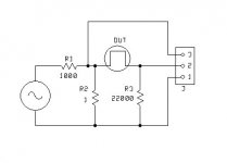
Attached is my test set up. I used an AP system 2 for the signal generator and have sent the signal across the cable both straight back into the AP set up to do FFTs and also tried it through a 1/2 step up transformer. The transformer version showed slightly different results but had lots of AC power line noise added.
(FFT Hamming window, 32K samples, 128 averages, .9F to 1.1F or tighter. Signal generator set for 7 volts.)
I tried test frequencies of 100, 300, 1K, 3K & 10K. I used two different cables. One was a 3' piece of 10 gauge THHN the other 3' 26 gauge 7 strand tinned copper hookup wire. Both pieces were folded in eighths to decrease loop area.
Probably will rerun with different current levels through the D.U.T.
Now the voltage out would increase with signal loss through the cable.
Just for JN the return path was the 22K resistor with total length under 2." The whole setup was built on the XLR connector without the shell.
Scott, I suggest you try this yourself.
ES
Attachments
Last edited:
Brad, things going up in flames does not make for great marketing with today's internet letting everyone know what is going on. At least in my case I'll be using material that meets UL-V5 flame rating which most other cheaper molded plastics have a hard time reaching those flame standards. It will char but typically not burn. JBL or Harmon would never pay for a heavy thick walled structural plastic, cheap is always the way those guys go.
Oh, I wouldn't argue that a bit. Quite the opposite, I'm in full agreement. The only usefulness of these concepts in audio is either for trolling or promotion of scams. Or both.
No you're not. Whatever you're doing, you're not in agreement with me. You're as slippery in defence of the indefensible as any scammer.
This is electronics.
When we talk about charge, we mean electrons, because when we mean holes, we say so, and holes are electrons anyway. We don't mean positrons. That would be positronics (Asimov). We don't mean protons. You can have a proton beam, but conduction is so infrequently by proton beam that it would be considered of note. Ions, yes, but the charges these charge carriers carry are electrons.
When we ask 'how much charge?' we mean 'how many electrons?' not 'how many electrons, Oh, and by the way, they have mass too...' When did you last figure electron spin for a tube design? Recall Occam. No model should be more complex than is required for understanding of the problem.
Consider a metal plate capacitor operated in a vacuum. Is it more correct to say charge flows onto and off the plates or electrons flow onto and off the plates? These descriptions are interoperable. Yes, you could insist that I say 'charge in the form of electrons', but I don't do you the discourtesy of imagining that you thought I meant anything else.
We build up models in education. Complex models are built on simple models. For this reason alone simple models have value other than for trolling and scams.
...holes are electrons anyway.
No.
When did you last figure electron spin for a tube design?
When did I ever say that you should?
Electron hole ??
How could they get that wrong being on the internet ?
It's a nice place where an electron might like to take a vacation .... or -
The geek definition.
This stuff is everywhere , just like booze.
OS
How could they get that wrong being on the internet ?
It's a nice place where an electron might like to take a vacation .... or -
.whenever electron acquires energy sufficient to "move" from the valence band to the conduction band a free hole is created in the valence band, and hence, electron-hole pair is generated; when electron and hole recombine, electron-hole pair is anihilated.
The geek definition.
This stuff is everywhere , just like booze.
OS
In the first paragraphs the enormity is that pitch is seen as related to the speed of sound. 41Hz is 41Kz, regardless of the speed with which it transported through the air. I always stop reading as soon as I stumble over BS like that.
Honestly, I think you need to re-read that. That statement advocates that absolute frequency is not the most important when it comes to choose a clock to drive a digital audio system.
If all at this forum had this white paper as basis for understanding "jitter", life here would be a better place.
http://www.grimmaudio.com/site/assets/files/1088/picoseconds_or_ppm.pdf
//
There's a lot of good explanations in that paper, I agree, but the analogy between clock/jitter/speed of sound is not the best one. Surely we can agree that a 1 kHz tone recorded on a cold day still sounds like a 1kHz tone on a hot day?
Jan
Last edited:
One question regarding linear PSUs. I've noticed that every transformer, including the toroids, has some current passing even when it is unterminated, with the secondaries up in the air.
Specifically, I compared a British made 300 VA toroid from ILP with another 300 VA made locally. The ILP was passing 17 mA, the local one 5-6 mA.
What is this an indication of? Consequently, which one is better?
Specifically, I compared a British made 300 VA toroid from ILP with another 300 VA made locally. The ILP was passing 17 mA, the local one 5-6 mA.
What is this an indication of? Consequently, which one is better?
So no one interested in discussing the 4Q design any more ?
http://www.diyaudio.com/forums/loun...ch-preamplifier-part-ii-1371.html#post4332676
Patrick
http://www.diyaudio.com/forums/loun...ch-preamplifier-part-ii-1371.html#post4332676
Patrick
- Status
- Not open for further replies.
- Home
- Member Areas
- The Lounge
- John Curl's Blowtorch preamplifier part II