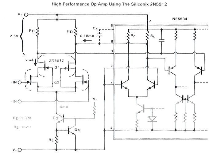
A NE5534 sounds even better when you replace its input stage with jfets by going through the compensation pins. Can anyone here figure out how to do that? We used to make them for Dave Wilson's WAMM Speaker System. That is perhaps the best that they can be.
Siliconix did this in an app. note back in the eighties. If I remember right they biased the input transistors in the 5534 to "off" and substituted them with jfets thru the compensation pins. I guess Google may be of some help if anyone wants to try this...
")
You got it right, 2quad. We tried it, and it worked! Especially subjectively. However it can be tricky and actually MORE noisy than using the 5534 in normal mode. Second stage noise can dominate, if you are not careful.
We made these for Dave Wilson to put into his CROWN Equalizer that he sold with each WAMM speaker system for some years.
We made these for Dave Wilson to put into his CROWN Equalizer that he sold with each WAMM speaker system for some years.
So I tried to find that app. note on the Internet, but no luck so far. I did find that this has been a theme at diyaudio before, though. And that people have answered to John's puzzle before me on this tread... I might have the old Siliconix databook deep down in my "analog" files. If my memory serves me right, Siliconix used a dual nfet for the job. 2N5912, I think. Was it a cascode with two 5912's? Many winters have passed since the last time i read that app. note...
John, have you ever tried this approach with more "modern" jfets? Others?
And how does this combo behave regarding latch up and phase reversal when driven into severe clipping?
John, have you ever tried this approach with more "modern" jfets? Others?
And how does this combo behave regarding latch up and phase reversal when driven into severe clipping?
Yes, dual 2SK170's are best. Gm R(load) is KEY. It cannot ever be the same level of gain as the original input stage, so second stage (noise compromises) creep in.
This is not the ideal op amp for everyone, but it does work. I don't know if it would latch, but there is no reason to, that I can predict. I have made hundreds of all discrete versions of this design and they don't give any trouble. The whole idea here is to keep the FOOTPRINT to an 8 pin package. Of course, cascode would be even better, but much harder to fit vertically.
This is not the ideal op amp for everyone, but it does work. I don't know if it would latch, but there is no reason to, that I can predict. I have made hundreds of all discrete versions of this design and they don't give any trouble. The whole idea here is to keep the FOOTPRINT to an 8 pin package. Of course, cascode would be even better, but much harder to fit vertically.
Vuki, the phenomenon i was talking about happens in other systems too, at least for my ears. A lot of recordings have to be centered with some kind of ballance control, be it a conventional ballance pot meter or seperate volume controls for both channels. When i only listen to music for personal enjoyment i can accept a good compromise and do not touch the controls.
Ideal is of cause a remote control that alows that. I personally do not like the integrated chips that can do that. I rather prefer switched resistors with relays but then comes the problem to find a relay that does no damage to the sound. That has being discussed here before. Motor potmeters are an option too and there are other ways. When i look at expensive linestages, they often have very sofisticated ways to adjust volume and ballance. I think it is a very critical part in the linesatge.
Ideal is of cause a remote control that alows that. I personally do not like the integrated chips that can do that. I rather prefer switched resistors with relays but then comes the problem to find a relay that does no damage to the sound. That has being discussed here before. Motor potmeters are an option too and there are other ways. When i look at expensive linestages, they often have very sofisticated ways to adjust volume and ballance. I think it is a very critical part in the linesatge.
The NE5534 looks a lot different now days, at least according to this OnSemi datasheet. I guess it's now NE5534/D?
On this one you'd have to tie pins 2 and 3 to the positive rail (pin 7) to accomplish the same modification.
ON Semiconductor
On this one you'd have to tie pins 2 and 3 to the positive rail (pin 7) to accomplish the same modification.
ON Semiconductor
The NE5534 looks a lot different now days, at least according to this OnSemi datasheet. I guess it's now NE5534/D?
On this one you'd have to tie pins 2 and 3 to the positive rail (pin 7) to accomplish the same modification.
ON Semiconductor
This data sheet is fulll of errors. The best 5534 was Raytheon MIL Spec. one of the old audio designer "secrets". Those are not PNP's on the input.
Last edited:
Just for fun i build a Fet cascode with things i had around. I think i got plausible results.
Standing current is a little under 1.7mA and i get an amplification factor of around 5.75 near clipping. Visible clipping is at 0.4V P-P in and that transfers into 2.3V P-P out.
Power bandwidth at that level is around 700kHz -3dB. I use 2SK246 with Idss of 4mA as the cascode Fet of a 2SK170 with an Idss of 7mA. Vds of the 2SK170 is a a very low 0.67V in this arangement although i use a high pinsh off voltage cascode Fet, so the spec sheet does not tell what happens here. For a phono MM input this could be usefull, but then i whould raise the 1kOhm resistor to 2kOhm or lower the 110 Ohm source resistor to 47 Ohm or something around there. With the lower source resistor it could be good for high output MC.
Attachments
Another way to get to the same place (almost) as John's JC2 phono stage http://rbsfm.ej.am/Downloads/Datasheet/LH/LH0032.PDF (but with bipolars on the output). The package is a little larger.
Yet another tutorial on FM.
https://ccrma.stanford.edu/software/snd/snd/fm.html
All sidebands are N*f1+-M*f2 there are people here who are interested in engineering without the vodoo.
https://ccrma.stanford.edu/software/snd/snd/fm.html
All sidebands are N*f1+-M*f2 there are people here who are interested in engineering without the vodoo.
I made a discrete OPamp but it is not aproved by JC sofar. At the moment it looks that i will not use it comercially, the PCB is big and it will be very expensive to make so i decided to publish the schematic. It has a high open loop bandwidth so follower of this thread may like it.
Just an idea : could FM intermodulation come from a PSU problem ?
Just an idea : could FM intermodulation come from a PSU problem ?
Attachments
- Status
- Not open for further replies.
- Home
- Member Areas
- The Lounge
- John Curl's Blowtorch preamplifier part II