Sorry I was blunt in my reply, I read your intention wrongly....
I said that the width of a via when converted to a equivalent trace width using the circumference is often wider than the trace. When you said the holes were not solder filled I presumed via's as other holes have a pin and solder in them usually.
For there to be distortion due to a PTH changing layer is strange and if so there must be some definable reason as to why it is so.
I suspect the plating is not as good an ohmic conductor as is the foil. In the test circuit (a 10 watt power amp) there may have been enough current differential to make it an issue.
But as you raise a good point next time I am ordering boards I'll try to include a test section with a series of through plated holes as a test sample.
I will also assume your boards get made at a high quality facility where some of mine get made at whoever is cheapest.
ES
Why ? Jitter is not recorded, only datas.once jitter is recorded it is hard to get it out in playback.
It is when your CD player read-it that it introduces Jitter. But, even there, no problem: don't read the flux from it, read the datas with a good re-clock.
That is what your PC is doing when you rip a CD.
CD player system is controlled by the CD player DSP master clock.Yes indeed, I went back and read the refs Richard posted a link to. The 2nd one, Bob Katz, after discussion the various ways a signal can pick up jitter during processing and transferring, he says that the in the final step it really doesn't matter because it's the DAC that determines the jitter during final conversion. This is a nice confirmation.
The first ref is completely wrong. The decision whether a bump/pit on a CD(R) is a one or zero depends on the pit/bump length. IIRC, the ratio of a zero to one bump/pit lenght is 1:3 to provide for some robustness in length variation. So the point he makes about the 'sharpness' of the bump/pit edges and relation to jitter is complete nonsense, he does not know what he is talking about.
Jan
Disc rotational speed is servo controlled in order to keep DSP FIFO buffer stage half full.
This FIFO buffer effectively removes playback recovered data speed variations due to disc rotational speed variation, and reflection (pit/land) transition point uncertainty.
The audio data output timing precision of the CDP DSP stage is directly according to the precision of the CDP DSP master clock/oscillator.
Any timing variation in the data feed to the DAC stage constitutes frequency (jitter) modulation of the audio output.
In typical consumer grade CD players, there are plenty of causes of DSP oscillator/clock timing variations (jitter).....power supply noise, ground noise, DSP chip internal noise etc.
Any timing variation of the recording ADC stage clock encodes frequency modulation in the decoded audio even if the playback clock is perfectly constant/precise.
So in practice, for digital record/playback systems, typically there are two imprecise clock oscillator stages effectively in series.
IOW, this means frequency modulated decoding of a frequency modulated encoded audio signal.
Somebody can do the maths, but as I understand it, level/spectrum of playback oscillator jitter exponentially interacts (intermodulates) with level/spectrum of encoded jitter causing a noisy cloud of IM products in the recovered audio.
This is why purpose built precision oscillators retrofitted to typical CD players make such a profound subjective improvement.
THD is not particularly affected, but IM products in the audio output can be quite dramatically improved.
This digital system noisy IM is what vinyl/analog listeners strongly object to, and not present in vinyl/tape systems.
Dan.
Jitter is contained in the original digital master.....it gets worse on playback.Why ? Jitter is not recorded, only datas.
It is when your CD player read-it that it introduces Jitter. But, even there, no problem: don't read the flux from it, read the datas with a good re-clock.
That is what your PC is doing when you rip a CD.
Dan.
This digital system noisy IM is what vinyl/analog listeners strongly object to, and not present in vinyl/tape systems.
Dan.
What you say is correct but once it's data, it's data, you can only make your playback as good as possible. You have to be kidding on your last point, George, PMA and I post every couple of months pictures of how bad vinyl spectra are, low frequency IM up the wazoo.
Hi John,
How long does it take to settle down to within 0.1 V? (just to get a rough number)
I am not suggesting you change your design. There are reasonable alternatives these days in case you needed to nail the output voltage down to a closer known voltage. The way you are doing things here may have some lot to lot dependance on the J-Fets used. Just guessing here as I have never even tried this. I will give it a whirl on a breadboard though - using a resistive load.
-Chris
Thanks, that explains why you do it this way. It makes perfect sense now.This regulator is SPECIFICALLY designed for the folded cascode gain stage. There is NO delta I, to speak of.
Or, you could use a buried zener designed for voltage references in test equipment. They are a lot more expensive than a normal zener. Series regulators would be AD581, AD584 or AD587 for 10 VDC that is quiet and does not tend to drift over time. Or go shunt (perfect direct swap) for ADR5044 (4 V) or LM4040C82 or LM4040D82 (8.192 V). Available in TO92 case style.Low noise is everything. Simple circuits are important too. Zeners don't work well. A true Zener would be under 4V so you would have to put 4 in series.
Very true, no argument there.The final design runs 24 hours/day, there is no significant temp change once the unit has been turned on for awhile.
How long does it take to settle down to within 0.1 V? (just to get a rough number)
I am not suggesting you change your design. There are reasonable alternatives these days in case you needed to nail the output voltage down to a closer known voltage. The way you are doing things here may have some lot to lot dependance on the J-Fets used. Just guessing here as I have never even tried this. I will give it a whirl on a breadboard though - using a resistive load.
-Chris
Yes, thats what I meant by retrofitting better clock/oscillators.What you say is correct but once it's data, it's data, you can only make your playback as good as possible.
Low frequency IM is the key...one can sort of live with that....up to a point.You have to be kidding on your last point, George, PMA and I post every couple of months pictures of how bad vinyl spectra are, low frequency IM up the wazoo.
I am saying that the higher frequency and erratic nature IM of digital gear is the problem subjectively.
More modern systems with much higher frequency master clocks reduce the subjective resultants, but it's still there...more a fine white noise jitter than a Fletcher Munsen concentrated jitter noise evident in older slower clocked gear.
Dan.
Originally Posted by john curl.
Wirewound is quiet with DC current flowing through it.
John has mentioned this a few times over the years.....no excess noise.Thanks.
se
I have a couple of eBay 10T WW pots with turns counters that I am soon to try as volume pots......likely not worse than the cheap carbon pots in use at present.
Dan.
J
I have a couple of eBay 10T WW pots with turns counters that I am soon to try as volume pots......likely not worse than the cheap carbon pots in use at present.
Excess noise is not an issue with volume pots since there's essentially no current running through them unless there's something seriously wrong with the design.
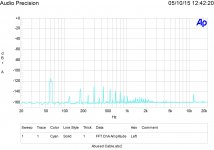
I took an 8" x 8" x 4" mild steel box and on side of the top plate placed a 24 volt center tapped transformer driving two 1N4007 diodes into a Nichicon 4700 uf/50V capacitor loaded with a 20 ohm 10 watt wirewound resistor. Ripple was 289 mV RMS. At the other end of the box top plate I put an RCA connector with a 100 ohm 1/2 W CC resistor connecting the center pin to shell.
I then did an FFT 20-20K of the output from the resistor. 0 dB = 2 volts.
Attached is the result.
I then did an FFT 20-20K of the output from the resistor. 0 dB = 2 volts.
Attached is the result.
Attachments
Last edited:
0.5V>5k=0.1mA.....Alps Blue, TKD, Noble, switched pots all sound different.....excess noise, wiper contact noise, which is it ?.Excess noise is not an issue with volume pots since there's essentially no current running through them unless there's something seriously wrong with the design.
Dan.
Last edited:

What's the gm of a J175?
gm=2*SQRT(Idss*Id)/|Vp|
Id is the drain current and Vp is the pinch voltage. If Id=Idss (no source degeneration) then gm=2*Idss/|Vp|
The data sheet will provide the numbers. For J175, gm will be anywhere between 5mA/V (Idss=7mA, Vp=3V) and 20mA/V (Idss=60mA, Vp=6V). That's not a small transconductance for a JFET. J176 and J177 will not do better in this respect, from the datasheet it is obvious they are the same device, sorted by Idss (gm is roughly the same for all of them).
Middle Finger Waving....
Try experimenting with oscillators, you may be surprised at the differences.
You could also have a yarn with Jocko...he is certain to set you straight.
Have you anything intelligent to say in place of reflex carping ?....time for you to grow up....alimony is expensive.
Dan.
Jitter measurement is well established.....just plain listening is another method, but you need to understand the sound of IM....get yourself some q-tips for starters.Have you figured out a way to measure jitter or is all this still handwaving?
Try experimenting with oscillators, you may be surprised at the differences.
You could also have a yarn with Jocko...he is certain to set you straight.
Have you anything intelligent to say in place of reflex carping ?....time for you to grow up....alimony is expensive.
Dan.
I think the phrase "recorded jitter" is being used too loosely. To me, the phrase ONLY refers to the jitter present from the act of converting the analog to digital. After that it is present in the signal, there is no way known to me to remove it. That is why the current recommendation is to clock the ADC from the internal clock which if well designed *should* be the cleanest.
for a primer on clocks and PLL's see Dan Lavry's white papers or Bruno Putzeys papers on the Hypex or Grimm sites.
for a primer on clocks and PLL's see Dan Lavry's white papers or Bruno Putzeys papers on the Hypex or Grimm sites.
Did you mean during AD conversions ? Digital desks are supposed to be quite good with the expensive master clock we, most of the time, use in studios. We use this as absolute time reference, and they are 're-clocked" to avoid phase Jitter.Jitter is contained in the original digital master.....
There is only one conversion, and the master will be the same ( for Richard ) whatever the future format: Datas.
[edit] Posted in the same time than waltzingbear, saying the same thing.
Last edited:
Yes, I do mean the original ADC clock.Did you mean during AD conversions ? Digital desks are supposed to be quite good with the expensive master clock we, most of the time, use in studios.
I have read reviews on studio mastering clocks sounding different !.
Dan.
the Masterlink swings back and forth over the line between prosumer and pro. Most people in the industry use it with external ADC and DAC, the included one sucks. It was adopted by the industry because it fit the bill to take care of some housekeeping without too much hassle, ie capturing a 2 track mix.
the optical drive is a data drive, it has changed over the years as availability has changes. Today it often uses a LG drive, there are usually several models to choose from.
Today the 9600 is very long of tooth. Limited in hdd capability (I think 32G limit). Never use any of the onboard processing, its bad. Dither? whats that?
Alan
- Status
- Not open for further replies.
- Home
- Member Areas
- The Lounge
- John Curl's Blowtorch preamplifier part II