Perhaps an overdesign, SY. Of course, I used bipolar transistors previously.
Why so? Was there a performance advantage? I would have thought that low rbb bipolars would work better, but I haven't compared them experimentally.
For the same overall voltage drop, a current source will always have more noise than a resistor passing the same current. This is because the resistor in the current source has to be smaller than the simple resistor, in order that the current source has room to operate, and that resistor's current noise is proportional to the reciprocal of the square root of the resistance. As well, the active device will have some voltage noise of its own, and this will produce an additional uncorrelated noise current density of e sub n divided by the resistance. And we are assuming a perfect reference voltage for the control electrode of the active device, which is also never the case. If the active device is a bipolar there will be additional noise from shot and excess noise in the base current.I thought current sources could be made quieter than resistors. Is this a myth?
There are some modest subsidiary noise (and other) benefits from the use of sufficiently quiet current sources in circuits like JC showed in post 67475, such as lower noise gain from the cascode transistors.
May-be we are not too much or too many really involved in very low noise circuits for vinyls or microphones ?The silence is disconcerting!
We, most of us, are living in a digital world.
Your circuit is elegant. I believe some aspects can be improved, but it always will be in compromising something else. Like distortion/noise, indeed.
I imagine, for my uses, i should had added current sources, for your use a cap multiplier to clean the rails. What else ?
Using-it as the input stage to build an operational amplifier with feedback ?
Last edited:
The silence is disconcerting!
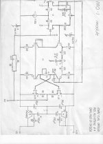
However, here as a noise model that we have to address to see what ACTIVE loads do wrong, much of the time.
Going back to original John's circuit and ignoring noise issue for a moment, why would one want to put the current source in place of resistor there?
It reduce distortion and increase PSSR.Going back to original John's circuit and ignoring noise issue for a moment, why would one want to put the current source in place of resistor there?
For the same overall voltage drop, a current source will always have more noise than a resistor passing the same current. This is because the resistor in the current source has to be smaller than the simple resistor, in order that the current source has room to operate, and that resistor's current noise is proportional to the reciprocal of the square root of the resistance. As well, the active device will have some voltage noise of its own, and this will produce an additional uncorrelated noise current density of e sub n divided by the resistance. And we are assuming a perfect reference voltage for the control electrode of the active device, which is also never the case. If the active device is a bipolar there will be additional noise from shot and excess noise in the base current.
There are some modest subsidiary noise (and other) benefits from the use of sufficiently quiet current sources in circuits like JC showed in post 67475, such as lower noise gain from the cascode transistors.
How would this compare to an RC bootstrapped current source?
chaps when u get a chance ... i havent seen this erik margan paper linked on the forum (although lots of discussion on his older papers on similar topic)
http://www-f9.ijs.si/~margan/Articles/Amp_Distortion_Dynamics.pdf
Quote from the final page:
... Because the open loop bandwidth of an ordinary amplifier is somewhere between 10 and 100 Hz, the reaction time is slow, and at high signal frequencies a large difference between the input and output signal
appears before the feedback loop is reestablished. Effectively this means that as the amplifier distorts, its bandwidth is reduced and its phase lag is increased, but once the signal amplitude falls below the quiscent threshold, the distortion is reduced considerably, and so is the phase lag.
What we have is actually a mechanism. Note that the amplitude of the switching phase modulation distorted signal follows the output signal amplitude, and the phase angle is practically constant (but within the first quarter of the first period, where the initial phase modulation occurs), until it suddenly vanishes.
How large is this pahse error? It is possible to calculate the phase angle from the arctangent of the imaginary to real component ratio, the real part being the output signal, and the imaginary part being the distorted signal in the bottom trace of . By observing the second period of the signal, where Fig.12 the phase relation is firmly established, we have about 0.1V in the distorted signal and about 4V in the output. The angle is then (180/pi)×arctan(0.1/4) = 1.5°. Not much, you will say. But bear in mind that
the human ear is insensitive to static phase shift, but very sensitive to quick phase changes.
{emphasis mine}
Note also that the amount of phase error is load impedance dependent, a dominantly capacitive load increases both the crossover distortion and the phase lag, a dominantly inductive load reduces both.
Also, the effect is increasing with signal frequency. With musical signals at moderate levels, this phase switching always occurs during the initial 10-50 ms or so at every start of a played note.
It may therefore be conjectured that this is the main cause for the often complained "stereo image instability" experienced during subjective evaluation, even if the of crossover distortion itself is unnoticeable."
Last edited:
Yeah, that's the pass devices I would have expected. What was the motivation to change? Did you see any improvements in performance or was this an esthetic choice (all FET stage)?
John?
I think I know what you mean, and that can work in some situations IF there is a low-Z drive for the capacitor driving the resistors. It's never quite as good as a dedicated active device source, but may be adequate for a number of apps. Here, we lack the low-Z drive for it.How would this compare to an RC bootstrapped current source?
SY, this is a difficult question for me to answer accurately. I just don't know. For more than a decade, before laying out this circuit, I used low rbb' complementary followers. They worked, but I always put a large electrolytic cap to ground AFTER the emitter, as well as in the base to ground. When I was forced to use only a 0.1 uf cap on the output of the regulator, I decided it was probably quieter to use a jfet follower. The input board was actually laid out to use 2SK146, 2SJ73 pairs for the series pass devices. Later, I switched to higher Idss j113") , J271(p) parts to allow for more total current. It has remained that way for 30 years.
, J271(p) parts to allow for more total current. It has remained that way for 30 years.
It would be interesting whether a good bipolar would be as quiet, WITH only a 0.1uF cap at the output of each follower. Perhaps one of the PhD's in engineering out there can give me a definitive opinion. By the way, is this the broken section in the Vendetta you are repairing. If so, check the 0.1uF cap. They sometimes short, which blows the follower.
, J271(p) parts to allow for more total current. It has remained that way for 30 years. It would be interesting whether a good bipolar would be as quiet, WITH only a 0.1uF cap at the output of each follower. Perhaps one of the PhD's in engineering out there can give me a definitive opinion. By the way, is this the broken section in the Vendetta you are repairing. If so, check the 0.1uF cap. They sometimes short, which blows the follower.
fet CCS.... with a low Rdson helps.
THx-RNMarsh
A suitable fet with Rs and gate tied to Rs/PS can be very low noise ccs. With Rs being low value if fet is chosen wisely.
http://arxiv.org/pdf/1012.5898.pdf
But then you can arrange IPS to act as thier own fet ccs with no extra noise penalty.... like in your newer designs.
THx-RNMarsh
Last edited:
Bootstrap sucks! Really, no kidding.
Got it.
By the way, is this the broken section in the Vendetta you are repairing. If so, check the 0.1uF cap. They sometimes short, which blows the follower.
The most difficult-to-diagnose and repair problem I had with a very elaborate detector system was due to a ceramic disc 0.1uF cap failing with high leakage. It was one of the few parts in the system that were sort-of-commodity, and it totally bit me. The other parts were in many cases Gov. Excess Property, hoarded by a brilliant albeit crazed professor of Zoology who kindly bestowed them on us.
The cap was just a HF bypass across a resistive voltage divider. But the high leakage screwed everything up, in a complicated pulsed-reset preamp's d.c. correction system.
It failed at a most inopportune time, as we had signed up to observe on a Mount Wilson telescope. I nearly killed someone when I was teased about it (I had some enemies, and some very juvenile ones).
- Status
- Not open for further replies.
- Home
- Member Areas
- The Lounge
- John Curl's Blowtorch preamplifier part II