That's a non sequitur. Adding a linear filter does not increase harmonics nor add new ones. Dick saw new harmonics and attributed it to DA. That makes no sense, but if he can recall exactly how that connection was established, that would be interesting to know.
It was done on the DA voltage of the polar cap iirc and with a LeCroy scope with built-in FFT. Dont quote me on that..... it was a loaner and had it for one session. Just something to think about during your sim. I might be able to find the model number of it.... but it is long obsolete by now.
Maybe doing sim's will discover something else which will be useful.
THx-RNMarsh
Last edited:
I've given everyone far more info than i ever wanted to...... every time an issue is brought up, I remember something about it which I had completely forgotten about.
You have sim..... go for it. I got circuit testing to do....... a direct-coupled, servo'd circuit, BTW.
")
THx-RNMarsh
You have sim..... go for it. I got circuit testing to do....... a direct-coupled, servo'd circuit, BTW.
THx-RNMarsh
Hmmm ... it comes down to there being good capacitors and bad capacitors for audio, and a "good" one can instantly be a "bad" one, by there being a glitch in the production facility for a day or so, in the manufacturing process, which is not enough to be picked up by the standard QA procedures.
Getting hung up on having the right numbers for a sample set of a certain electronic part is never going to solve things - if the end product is not right then there is a reason ... which may very well be due to a dodgy bunch of a particular part - as well as, the myriad of other factors ...
Getting hung up on having the right numbers for a sample set of a certain electronic part is never going to solve things - if the end product is not right then there is a reason ... which may very well be due to a dodgy bunch of a particular part - as well as, the myriad of other factors ...
We are in an audio forum. Remember, fashion. I said distortion = change of the signal form. Audio signal is not often a pure sinus. And distortions not only always adding harmonics to it.Adding a linear filter does not increase harmonics nor add new ones.
Of course a linear filter can increase or decrease existing harmonics in a signal witch have some.
Really? I have not seen any proof that DA is the distortion mechanism. I have also made a lot of capacitor measurements, but would not say distortion was a result of DA.
DA makes longterm time domain errors, in frequency domain errors at very low frequencies, most probably linear errors rather than non-linear distortion.
My view is that if the AP shows no distortion, there is no distortion.
Dick was talking about nonlinearity and showed a harmonic plot. Perhaps it might be better to address his data and arguments rather than imaginary ones.I said distortion = change of the signal form. Audio signal is not often a pure sinus. And distortions not only always adding harmonics to it.
You raise a good issue. Standard practice is to put capacitors across each diode. I have seen 10 nF suggested as the value.
JC of course uses a diode that has low switching noise.
I forgot to make one thing clear, this discussion is about low power supplies as would be used in preamps!
There are so many places to start the discussion.
AC mains noise?
Avoiding unbalancing the transformer?
Diode noise?
Transformer noise?
Surge currents?
Ripple?
Filtering vs frequency?
Circuit theory components not shown in the schematic?
...
ES
Oh ****. Here we go again.
Dick was talking about nonlinearity and showed a harmonic plot. Perhaps it might be better to address his data and arguments rather than imaginary ones.
I talk about distortions.... you talk about nonlinearity.
Too bad you dont sim. But maybe someone else here does and we can all watch, learn and listen.
I'm passing the baton to the sim masters.
THx-RNMarsh
Last edited:
Sim'ing is good - I made a lot of progress, realising where some very nasty distortion mechanisms were in place, which are normally largely ignored, on the basis that "we don't worry or think about those things" ... adjusted the circuit, in sim, to minimise those problems, and then carried it through to the real world. Surprisingly, this resulted in very worthwhile subjective results, considering this is probably "handwaving" engineering, ...
...I talk about distortions.... you talk about nonlinearity.
The data you showed was a distortion spectrum showing harmonics. That's nonlinearity by definition.
The data you showed was a distortion spectrum showing harmonics. That's nonlinearity by definition.
Yup. Before he even showed the plots, he specifically said "H2" and I'm pretty sure he didn't mean hydrogen.
se
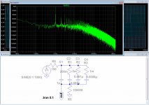
Lets go. (I'm not the king of the simulation, so if anything wrong, please tell-me):IToo bad you dont sim.
Attachments
Last edited:
Let go. (I'm not the king of the simulation, so if anything wrong, please tell-me):
Where's the non-linear element in your circuit that's producing the harmonic products?
se
Yup. Before he even showed the plots, he specifically said "H2" and I'm pretty sure he didn't mean hydrogen.
se
yes, I mentioned and explained that was from the FFT on the Vda. Of a polar cap.
Distortion(s) of the non-linear type can be found in more complete form by tests from C.bateman. he did a good job. But not really identifying the mechanism which caused the distortion.... which i think is at the heart of SY's questions.
[BTW - which line # is it that I showed the plot? To be sure you are interpreting what I put it to illustrate. But, thd or FFt of caps in general I havent done myself.... See C.Bateman. He and others measured different 'types' of caps for thd distortion. ]
You have to have a voltage developed across them. You can use sine wave along with freq vs RC to get the drop across it or a unipolar pulse.
THx-RNMarsh
Last edited:
DA tet with uni-pulse.
The pulse for signal was chosen for 2 reasons....... it is not symmetrical and it was impulse shape like a lot of music transients are. resembled music waveforms.
No other reason than that. It turns out to be a very sensitive test for caps.
As with all tests of parts -- we only test one part.... but the amp is composed of many of such parts. IOW, the total is much higher than a single part test would show. Anyway....
A single pulse level of Vda looks a lot different when you pulse it frequently/repeatedly in that DA test. The Vda adds to each and grows higher. If the polarity of the uni-pulse is reversed every so often, the Vda subtracts from the previous Vda and so forth making a complex waveform not a part of the simulated music signal - pulse but related to it. If you alternated the PS so that the pulse alternated in polarity and the timing was not varied.... the Vda would tend to cancel itself out or average towards minimum.
This should be looked at in sim. But still doesnt answer SY's question. Just interesting factoid and observation during the testing with the pulse signal.
Part of the complete model is an added element to the esr. At low freq, the esr is mostly just that of the bulk metal. but as freq go higher, the dielectric material adds some R of its own to the esr so that esr appears to increase with freq. It appears to do so in an exponential manner.
THx-RNMarsh
Last edited:
yes, could save pages of posts if several would simply read it, think about it even a little
Esperado's DA circuit sim is fairing poorly due to LTSpice sim setting - easily corrected
despite his allergic reaction to me I don't hold ignorance of the SW peculiarities against him - just his previous unwillingness to learn, correct other sims he has posted when the errors were pointed out
if you understand the EE Linear System principles you know to debug your sim if it shows nonlinear components in a LTI modeled system
good theory should even lead you to debug/rethink your physical experiments when results deviate too much from previously documented effect's magnitudes
- Status
- Not open for further replies.
- Home
- Member Areas
- The Lounge
- John Curl's Blowtorch preamplifier part II