BTW, am-i wrong in supposing the distortion of ceramic caps is due to mechanical resonance of the ceramic ? If i'm not, did SMD reduce the effect ?
I do not think so, there is a plain dependence of capacitance on voltage as well.
Ed you have a unique and personal way of looking at things. You could also notch out the fundamental and have huge THD. BTW the cap ladder model for DA works fine at DC (yes I know there is "no" DC) and AC there is no need to bring in the "time from the creation of the universe". You will find that the DA in most cases contributes small fractions of a dB frequency response anomalies, after all we needed a G100-G1000 amplification to see anything.
Ah, now we are communicating. If you have a specific capacitor with known high DA it may be worthwhile to do a low end frequency sweep (level and phase) to verify the actual changes. No a simulation is not really proof at an extreme case. (Although it could be right, but until verified...)
(We can ignore mostly below 2 hertz as that probably won't have any influence on our perception of music reproduction.)
The other issue is "Does high DA ride in with other bad guys?"
Last edited:
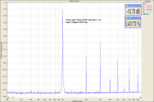
This is the distortion behind 100nF ceramic capacitor, on load resistor terminals, C-R, R = 1k, C = 100 nF, filter input voltage 0.635Vrms. With mylar 100nF, distortion fell down to 0.002%.
Pavel,
If you have enough of those capacitors you can sell them at quite a premium as Audiophile grade!
ES
Thanks, Pavel.This is the distortion behind 100nF ceramic capacitor.
Do you have compared with "ePhone Age" ones ?
That is an excellent piece. I wish he didn't lump all ceramics together. Note the explanation of hook as water in the material (hadn't seen that before).Completely is relative, it enabled 20bit integratiing A/D's (ppm level linearity) ~40 yr. ago with this simple model.
Here is an historical overview and Cadences' models. Ken is a smart guy, this is more than you would ever want to know and the most complete DA modeling treatment I have seen. I could not find any non-linear elements here not that I read every word.
http://www.cktsim.org/Modeling/da.pdf
But again, without a voltage-dependent change in one or more parameters, there is no mechanism for nonlinear distortion, only frequency response alterations (which, indeed, many do call "linear distortions").
When Anthony New, an RF engineer, decided to illuminate all of us stupid audio folk about intermodulation distortion in the pages of Electronics World (UK) some years ago, he emphasized that harmonic distortion of a single musical note was indistinguishable from a change in timbre (not his words precisely, but I believe that was the gist). What he failed to note was how, beyond simple one-number THD specifications, audio equipment is measured routinely for IM (let alone other tests for things like TIM), and with his extraordinary ignorance berated us for not performing such tests.
What could provide the nonlinearity/nonconstancy in a capacitor to generate nonlinear distortions? How about any mechanism that causes the capacitance to vary with voltage, such as motion of the plates due to attractive/repulsive forces? Note that this can be a small-signal linear variation in the capacitance as a function of voltage. One cannot get it from a construction of constant capacitances and resistances.
Parenthetically, although we throw the terms linear and linearity around as if they were well-understood, I doubt that many do really understand them. We are vexed with misnomers like transistors that have "linear beta", I suspect started by the Japanese as a mistranslation, where what is accurate is "constant beta" (as a function of collector current). Yes, it is true that y = mx + b, the slope-intercept form of a linear equation, does have a solution for m = 0, but this is a degenerate case.
Perhaps it is time for Bruno or someone to write a piece for Jan's magazine called "The L Word".
I think maybe you've spent a bit too much time at the pub.
.......................
se
I often wish that he would spend all of his time there .... in one with no internet facilities that is!
Thanks, Pavel.
Do you have compared with "ePhone Age" ones ?
Not in the detail, in fact. I was just happy that MKP, MKT and COG/NPO capacitors do not distort under normal conditions. But I have an interesting article re "iPhone Age capacitors", please find it attached.
Attachments
This is the distortion behind 100nF ceramic capacitor, on load resistor terminals, C-R, R = 1k, C = 100 nF, filter input voltage 0.635Vrms. With mylar 100nF, distortion fell down to 0.002%.
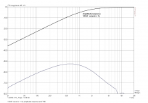
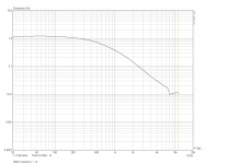
No doubt - but you are showing a highpass with 1,6kHz corner frequency. That is far from real audio coupling at least a factor of 100x below that.
That is an excellent piece. I wish he didn't lump all ceramics together. Note the explanation of hook as water in the material (hadn't seen that before).
See my upcoming LTE in Linear Audio. This is a very overlooked factor and can explain, e.g., the aging phenomenon of PET caps reported by Self.
That's amazing that manufacturers can call anything a given dielectric if it merely passes tempco. Pure evil!Not in the detail, in fact. I was just happy that MKP, MKT and COG/NPO capacitors do not distort under normal conditions. But I have an interesting article re "iPhone Age capacitors", please find it attached.
That is an excellent piece. I wish he didn't lump all ceramics together. Note the explanation of hook as water in the material (hadn't seen that before).
But again, without a voltage-dependent change in one or more parameters, there is no mechanism for nonlinear distortion, only frequency response alterations (which, indeed, many do call "linear distortions").
When Anthony New, an RF engineer, decided to illuminate all of us stupid audio folk about intermodulation distortion in the pages of Electronics World (UK) some years ago, he emphasized that harmonic distortion of a single musical note was indistinguishable from a change in timbre (not his words precisely, but I believe that was the gist). What he failed to note was how, beyond simple one-number THD specifications, audio equipment is measured routinely for IM (let alone other tests for things like TIM), and with his extraordinary ignorance berated us for not performing such tests.
What could provide the nonlinearity/nonconstancy in a capacitor to generate nonlinear distortions? How about any mechanism that causes the capacitance to vary with voltage, such as motion of the plates due to attractive/repulsive forces? Note that this can be a small-signal linear variation in the capacitance as a function of voltage. One cannot get it from a construction of constant capacitances and resistances.
Parenthetically, although we throw the terms linear and linearity around as if they were well-understood, I doubt that many do really understand them. We are vexed with misnomers like transistors that have "linear beta", I suspect started by the Japanese as a mistranslation, where what is accurate is "constant beta" (as a function of collector current). Yes, it is true that y = mx + b, the slope-intercept form of a linear equation, does have a solution for m = 0, but this is a degenerate case.
Perhaps it is time for Bruno or someone to write a piece for Jan's magazine called "The L Word".
... or read Cyril Bateman's Capacitor tests in Vol 9?
Jan
Attachments
Last edited:
That's amazing that manufacturers can call anything a given dielectric if it merely passes tempco. Pure evil!
Wish it was ONLY a tempco.
I think you need an article about what linearity is and why it is important.... or read Cyril Bateman's Capacitor tests in Vol 9?
Jan
No doubt - but you are showing a highpass with 1,6kHz corner frequency. That is far from real audio coupling at least a factor of 100x below that.
You are right, but you may have filter applications as well. And you will definitely prefer a part that distorts 0.002% in your app than the part that has 0.43%.
Attachments
... or read Cyril Bateman's Capacitor tests in Vol 9?
Argh! I think Jam has my Vol. 9. Or did I forget to order it? I seem to recall seeing it. If I ordered it, could you email me a PDF of the article so I can refresh my memory. If I didn't, let me know and I'll order it.
Thanks!
EDIT: Nevermind. Just saw that you edited your post and included the PDF.
EDIT: Oh, I see it was just the one plot. So original post is back in effect.
se
Last edited:
I think you need an article about what linearity is and why it is important.
Consider yourself invited
Jan
The distortion of the capacitors is a very tricky thing. The nonlinearity of the ceramic ones is quite common. But the film ones can also distort due poor technology, if the foil isn't tighten sufficiently. Then something like electrostriction can appear, no matter which dielectric is used. The sintered polystyrene is the best solution in general including the stability, tempco and dielectric absorption, but such parts are very hard to obtain. Another way is the oil capacitors.
- Status
- Not open for further replies.
- Home
- Member Areas
- The Lounge
- John Curl's Blowtorch preamplifier part II