If amplifier output voltage had the same nonlinearity as speaker impedance, then speaker current would be undistorted. Crazy. But unrealistic.
There are folks trying to do this with DSP. So far the results are what you would expect. Sounds great to the experimenters, not so much to others.
Hmmmmm. When you put 1 Ohm in series the measured distortion increased. No?
As far as I am concerned.... this is similar to a cable placed in series... though less complex.
It isnt theory -- it is measured that I refer to. Low distortion at the amp terminals and higher at the speaker terminals with zip cord in between terminals.
Do I understand correctly that regardless, there is no net increase in distortion from the speaker output and no effect on any amplifier either?
THx-RNMarsh
Based on Esa Merlainen's ideas, if the cable impedance results in a distorted waveform at the speaker terminals, this will actually decrease the distortion at the speaker itself because it is actually resisting the back-EMF signal which contains distortion. If you allow the back-EMF to discharge through a low impedance, the distortion in it adds to the distortion in the output of the speaker.
Of course if you try to use current drive with a speaker with a crossover, the crossover will probably ruin your work because it will shunt the back-EMF.
Sighhh ... okay, let's go to where the word "smart" can be applied to the content of the material, rather than other aspects of the "message" ... hmmm, www.klippel.de/uploads/media/KLIPPEL_Small_Loudspeakers_-_heyser_lecture_rome_AES_134th_.pdf ... not bad ...
If amplifier output voltage had the same nonlinearity as speaker impedance, then speaker current would be undistorted. Crazy
The distortion in a simple woofer under normal operation is mostly from the motor. That is exhibited by a non linear BL or force per Amp vs position.
The speaker Motor’s back emf or Voltage per velocity is tied to the force sensitivity ie; force per Amp or BL.
Actually one can do more than that.
The impedance is a series resistance connected to a transducer where the Current proportionally converts into force and the back emf it generates proportional to the Velocity of the moving conductors. Here, the higher the BL or force per Amp, the greater the voltage it generates at a given velocity. These things are called up in greater detail in the Servomotor area where Kt= torque per Amp.
The point is, you can control what is happening using an old DC motor trick to regulate speed, negative impedance and in the loudspeaker can reduce some distortions. Say you have a simple DC motor that produces 12 volts per thousand rpm as a generator, when you connect it to a 12 V battery, it turns 1000 RPM but then when you add a load, it slows down.
A solution can be a simple current sense resistor in the ground leg and you add some of that current sense voltage as positive feedback at the input. When you adjust that amount, you can set it to be adding an extra voltage exactly the same value as would be lost across the motor’s internal Rdc. Now when you add the load, the speed falls slightly BUT that reduces the back emf forcing more current to flow and that current adds the force needed to bring the speed back up to where it was or very nearly.
In the old days before T&S parameters and stiff voltage source amplifiers, they often had an output impedance adjustment and I still have an amplifier Crown made of the Armstrong variety called a Delta Omega that had an adjustable impedance positive or negative.
I should say too that in the T&S parameter world, you are tossing the old effective Qe etc out the window.
The point is, once you take away what you know is happening across a resistance, the Rdc, what the motor is doing motionally becomes clear and I should stop there.
Best,
Tom Danley
Last edited:
My intuitive solution, without understanding all the mechanics, was/is to shorten the cable length---- either with the amp beside the speaker cabinet or inside the speaker cabinet. And, to use seperate amps and electronic cross-over..... today DSP,perhaps. The experiement I did was to locate the amp a few cm/inches from the speaker terminals and place a small jumper between amp output and speaker. this was called the No-Cable setup and was compared by switching in the long speaker cable with the amp physically in same location next to the speaker. There was a difference detected. Apparently, the cable interface's series Z is not only important for damping issues but for distortion via counter emf with the power amp OPS..... which might be the dominate element. The sound was also brighter.... perhaps due to lower Ls in series with the tweeter L.
Today, I understand, with the help of others, that isolating the OPS from the internal gain stages is a part of this same issue. The rapid spread of wireless (cable-less) may be a good thing for many reasons.... but will bring new issues to overcome.
THx-RNMarsh
Today, I understand, with the help of others, that isolating the OPS from the internal gain stages is a part of this same issue. The rapid spread of wireless (cable-less) may be a good thing for many reasons.... but will bring new issues to overcome.
THx-RNMarsh
Last edited:
Indeed it might - I heard the new Dynaudio wireless speaker at that audio show, and sorry, it was pretty dreadful - unpleasant midfi ... don't the people who set these things up have any ears, at all ... ?Today, I understand, with the help of others, that isolating the OPS from the internal gain stages is a part of this same issue. The rapid spread of wireless (cable-less) may be a good thing for many reasons.... but will bring new issues to overcome.
Last edited:
Lets find out further ........ but surely isolating the OPS and speaker from the internal gain stages is a plus. What is the consensus when listening to a 1 Ohm resistor inserted in the speaker line? Someone must have done that and can tell us. And, we can take it aprt from there? I think someone said it sounded better/cleaner? Multiple mechanisms going on..... so first use an amp with best OPS isolation then do further inquiry re voltage/current source.
THx-RNMarsh
THx-RNMarsh
I have a question on jfets to which I haven't yet found a good answer. Given that all the Jfet gurus are on this list I wanted your advice:
For jfets in a conventional differential input stage, what is the optimal bias condition for each jfet ?
I *think* it would be 50% of Idss - is that correct ?
For jfets in a conventional differential input stage, what is the optimal bias condition for each jfet ?
I *think* it would be 50% of Idss - is that correct ?
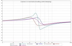
Funny to see amplifier guys talk about speakers.. this interaction is absolutely the core and much can be done on the speaker side to reduce these issues in the current domain.
For one thing it highlights exactly why speaker design by resonance is a really bad idea. It also shows that VC inductance is really bad and why dynamic effects in the speaker and drivers are to be reckoned with.
this interaction is absolutely the core and much can be done on the speaker side to reduce these issues in the current domain. For one thing it highlights exactly why speaker design by resonance is a really bad idea. It also shows that VC inductance is really bad and why dynamic effects in the speaker and drivers are to be reckoned with.
Lets find out further ........ but surely isolating the OPS and speaker from the internal gain stages is a plus. What is the consensus when listening to a 1 Ohm resistor inserted in the speaker line? Someone must have done that and can tell us. And, we can take it aprt from there? I think someone said it sounded better/cleaner?
THx-RNMarsh
It's too low. If you're using an 8 ohm speaker you've already got 8R resistance in series with the coil rejecting the back-EMF. Add 1R and it's just a 1/8 increase, very unlikely to have much of an effect except at bass.
My speakers have peaks up to 33 ohms. So a 33R series resistor would reject only 50% of back EMF at those frequencies. But, you waste most of the power in the series resistor.
One thing I did was I used a 25R resistor for a fullranger and then used EQ to flatten the response. This might give interesting results but it's still many times less effective than an amplifier designed to have 1k or more output impedance.
The only cure would be a current drive with frequency response equalization. The last is not easy near to driver resonance.
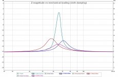
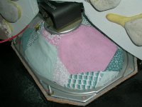
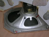
Driver’s main resonance can be tamed quite effectively –at least with some drivers- by the simple old ‘trick’ (*) of covering the basket with a cloth
Today, I understand, with the help of others, that isolating the OPS from the internal gain stages is a part of this same issue
Richard
Can you provide a link to the thread that this is discussed?
George
(*) It has been analyzed by R. Small
Attachments
Funny to see amplifier guys talk about speakers..
I am an "amplifier guy" graduated in electro-acoustics
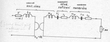
. So, the fact that speaker lumped element model (with almost all elements non-linear) is driven by current is no news.----
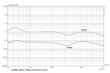
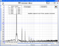
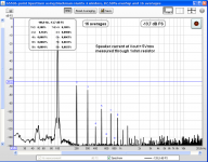
Re 1 ohm "isolation" - it makes almost no difference. One more measurement, amplifier output voltage and speaker current. This time, for output voltage measurement, speaker was connected directly to amplifier terminals, without 1 ohm resistor. Speaker current was measured through 1 oh resistor again. We can see again that current distortion is about 20x higher than voltage distortion = result of nonlinear speaker impedance.
Attachments
Driver’s main resonance can be tamed quite effectively –at least with some drivers- by the simple old ‘trick’ (*) of covering the basket with a cloth
I assume you would not like to do the same with woofers, George
Resonance is not everything. Le (voice coil inductance) is non-linear and many other elements as well.
The point is, you can control what is happening using an old DC motor trick to regulate speed, negative impedance and in the loudspeaker can reduce some distortions. Say you have a simple DC motor that produces 12 volts per thousand rpm as a generator, when you connect it to a 12 V battery, it turns 1000 RPM but then when you add a load, it slows down.
A solution can be a simple current sense resistor in the ground leg and you add some of that current sense voltage as positive feedback at the input. When you adjust that amount, you can set it to be adding an extra voltage exactly the same value as would be lost across the motor’s internal Rdc. Now when you add the load, the speed falls slightly BUT that reduces the back emf forcing more current to flow and that current adds the force needed to bring the speed back up to where it was or very nearly.
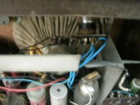
Here is an attempt at doing that, including thermal compensation for the resistivity of copper (two first pics).
http://www.diyaudio.com/forums/solid-state/165867-servo-sound-made-belgium-2.html#post2169312
It is the absolute opposite of current drive: it transforms the voice coil into a superconductive one
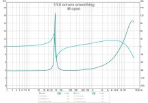
Probably my last measurement on this topic. Now at 5Vrms amplifier output voltage. Both spectral measurements were equalized to almost same level of fundamental harmonic component, within 0.1dB. Direct comparison is possible now.
First number is for voltage distortion, second for current distortion.
THD 0.024% 0.188% (7.8 x more)
2nd 0.023% 0.163% (7 x more)
3rd 0.006% 0.09% (15 x more)
7th 0.0002% 0.0037% (18.5x more)
First number is for voltage distortion, second for current distortion.
THD 0.024% 0.188% (7.8 x more)
2nd 0.023% 0.163% (7 x more)
3rd 0.006% 0.09% (15 x more)
7th 0.0002% 0.0037% (18.5x more)
Attachments
John thanks that's very clear.At first cut, 50% of Idss is recommended. For ultimate performance, more than 50% is possible with HIGH Gm jfets, but pretty good performance can be gotten with less than 50% Idss, down to 20% or so, but there will be somewhat more intrinsic distortion generation.
So, we're back to the holy grail of amps - they should act as ideal voltage sources, however into low impedance loads as well as higher impedance loads. For example, they should be able to deliver their nominal voltage even into 2 Ohms, at the very least as peak power, if not as RMS. With inaudible distortion.
Richard says with short cables. I agree, but unfortnately some room simply force you to use longer cables, my room needs 6 m (app 20 ft) of cabling. My wife's system is just fine with 2.5 m (app.8.5 ft) of cable.
If you need loger cable, to compensate you need thicker cable. I use 5 mm2 2*256 strand cable, as recommended by Ben Duncan's book on amplifiers. It all well and fine that my amps can deliver a whole load fo current, but I need something to carry all that current to the speakers, and a teeny weeny cable won't cut it.
- Status
- Not open for further replies.
- Home
- Member Areas
- The Lounge
- John Curl's Blowtorch preamplifier part II