Japan has at least two types of plugs and those without grounding stick may be inserted in both ways ....
An externally hosted image should be here but it was not working when we last tested it.
A Zener is always rated at a voltage below 6.2V. The higher voltage devices work on a different principle and are usually VERY noisy.
Attachments

Pavel,
That is a fairly common non polarized two prong plug but these days you do see two prong plugs often with one larger lug so it will only allow insertion one way into a wall socket. The real problem with that is who says the wall outlets are wired correctly, I would bet it is a 50/50 odds they are reversed in most homes, most electricians don't seem to pay any attention to polarity, hot and neutral is what is common here in our 110V house wiring, just as long as they get the green ground wire right that seems to be about as far as they are paying attention! So now you would have to go and check any outlets to see if the plug matches the outlet polarity and fix it. I imagine if you are using more than one wall outlet and the outlets are wired in reverse this would be one cause for some weird ground looping going on between outlets and pieces of equipment.
That is a fairly common non polarized two prong plug but these days you do see two prong plugs often with one larger lug so it will only allow insertion one way into a wall socket. The real problem with that is who says the wall outlets are wired correctly, I would bet it is a 50/50 odds they are reversed in most homes, most electricians don't seem to pay any attention to polarity, hot and neutral is what is common here in our 110V house wiring, just as long as they get the green ground wire right that seems to be about as far as they are paying attention! So now you would have to go and check any outlets to see if the plug matches the outlet polarity and fix it. I imagine if you are using more than one wall outlet and the outlets are wired in reverse this would be one cause for some weird ground looping going on between outlets and pieces of equipment.
Dimitri,
Sometimes people don't react because nothing new is told, or what is told is known to be wrong ...
")
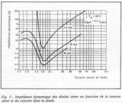
The minimum at around 6.8V in dynamic impedance is quite well known.
That at that voltage, also the noise is minimum, is not correct I believe. But I could be proven wrong.
Jan
At least you noticed my PS regulator, nobody else did.
I don't see way to use capacitance multiplier for a preamplifier where no need for high current, when a shunt regulator is much better.
Yes, I did look at it.
Now if only you offered some PCBs for your design...
I hate point-to-point wiring unless it's a very simple circuit.
The minimum at around 6.8V in dynamic impedance is quite well known.
That at that voltage, also the noise is minimum, is not correct I believe. But I could be proven wrong.
I think noise min was at 6.2V, right at the zener/avalanche crossover.
Shunt regulators are, indeed, often better when generated noise is the target. But did they filter as well the HF and other parisitic signals coming from the AC ?I don't see way to use capacitance multiplier for a preamplifier where no need for high current, when a shunt regulator is much better.
As i said previouly, I believe some ground isolation is necessary.
The real problem with that is who says the wall outlets are wired correctly, I would bet it is a 50/50 odds they are reversed in most homes, most electricians don't seem to pay any attention to polarity, hot and neutral is what is common here in our 110V house wiring, just as long as they get the green ground wire right that seems to be about as far as they are paying attention!
I have not observed this, it's just too easy to stick one of those polarity check plugs in they all have them.
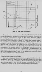
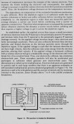
For clarification, a Zener diode, while available in a continuous range of voltages, actually operates on two principles: Zener and Avalanche. At about 5-6V these two effects cancel their relative temp coefficients and are the most stable under temperature changes. On either side of this range we get Zener diodes (primarily) below 6V or so, that can be very quiet, but have a significant tempco and fairly lousy regulation.
Above 6V, we get primarily Avalanche mode, with LOTS of extra noise and even again fairly high dynamic impedance (see Dimitri's graph). It is the NOISE that is almost overwhelming and it usually has to be filtered down to some reasonable amount like DVV's power amp schematic showed. ( By the way, I do all my power amps like that schematic. )
We are making progress, thanks for all your inputs, but one step at a time.
Attachments
Last edited:
I think noise min was at 6.2V, right at the zener/avalanche crossover.
Some data sheets from Maxim show a minimum at 4.8, flat going down, rising going up.
Few weeks ago, we discussed opamp loading and shown some examples of good behavior. Today, it happened to me to measure a conventional headphone output with NJM4565 opamp. 90% of consumer electronics would have it inside. Please see measurement without load and with 50 ohm load, at only 1V peak-peak (0.35Vrms). With 50 ohms, you may see purely crossover distortion - and it sounds exactly this way - sterile, aggressive, gray, harsh sound. I often wonder what the guys who make listening tests directly from PCs with headphones will hear.
Do you mean the NJM4556?
Scott,
I'd have to check but I think that except for some GF detector outlets they didn't pay much attention to this in older houses built before all these polarized plugs became common. My house was built in the early 70"s and I would be really surprised if they paid attention when wiring the house. But you are correct it would be pretty easy to correct this situation if you wanted to do that.
I'd have to check but I think that except for some GF detector outlets they didn't pay much attention to this in older houses built before all these polarized plugs became common. My house was built in the early 70"s and I would be really surprised if they paid attention when wiring the house. But you are correct it would be pretty easy to correct this situation if you wanted to do that.
Above 6V, we get primarily Avalanche mode, with LOTS of extra noise
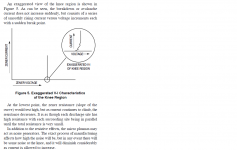
Christer at his diode testing thread has something to say on this
Zener diodes seem an altoghether different and more confusing
story. Below approximately 6V they have true zener breakdown
and above this they have avalanche breakdown. It was thus
obvious to test zeners close to and to each side of this
"transition region" and also zeners far into each region.
Surprisingly, the important distinction seems not to be which
type of breakdown they exhibit, but how close to or far away
from the transition they are. Low volt and high volt zeners
turned out to have moderate noise and the high voltage
avalanche type could even rival most LEDs. Those diodes
close to the transition, on the other hand, turned out to
be noisy as h**l
George
Christer at his diode testing thread has something to say on this
George
To be fair, you should really test them for noise when they are well into their avalance region, i.e. carrying appreciable current.
Depending on fabrication method a bit, but they are very noisy around the transition; sort of intuitive I think.
Intuition OK: see attached.
Moral: don't starve your zeners....
Jan
Attachments
Last edited:
About sens of the AC plugs, there is no standard on the way trasfos are wired in an amp, neither the polarity were they exhibit the less leakage. The only way i know is to test. I begin with the preamp, with no earth connection, and i chose the sens where there is the less voltage between-it and the earth.
Then i connect the power amp to the AC plug ( and no earth), and chose the sens where it exhibits the less voltage between the ground of his input and the ground of the output of the preamp...then i connect the signal... and do the same with all the devices i use, one by one.
Then i connect the power amp to the AC plug ( and no earth), and chose the sens where it exhibits the less voltage between the ground of his input and the ground of the output of the preamp...then i connect the signal... and do the same with all the devices i use, one by one.
Last edited:
Dimitri,
Sometimes people don't react because nothing new is told, or what is told is known to be wrong ...
The minimum at around 6.8V in dynamic impedance is quite well known.
That at that voltage, also the noise is minimum, is not correct I believe. But I could be proven wrong.
Jan
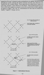
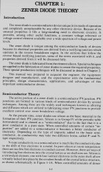
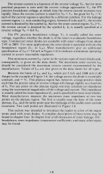
So this took a while. One of those old books (you know) is tittles 'Motorola Zener Diode Manual' and has a nice article about how it functions. Here it is (sorry about the quality this is the maximum file size that I could upload).
Attachments
-
 Zener Diode Theory 008.jpg494 KB · Views: 75
 -
 Zener Diode Theory 007.jpg606.3 KB · Views: 61
 -
 Zener Diode Theory 006.jpg568 KB · Views: 74
 -
 Zener Diode Theory 005.jpg561.1 KB · Views: 83
 -
 Zener Diode Theory 004.jpg509.8 KB · Views: 197
 -
 Zener Diode Theory 003.jpg728.1 KB · Views: 201
 -
 Zener Diode Theory 002.jpg372.3 KB · Views: 206
 -
 Zener Diode Theory 001.jpg636.9 KB · Views: 208
 -
 Zener Diode Theory 009.jpg562.5 KB · Views: 69
For clarification, a Zener diode, while available in a continuous range of voltages, actually operates on two principles: Zener and Avalanche. At about 5-6V these two effects cancel their relative temp coefficients and are the most stable under temperature changes. On either side of this range we get Zener diodes (primarily) below 6V or so, that can be very quiet, but have a significant tempco and fairly lousy regulation.
Above 6V, we get primarily Avalanche mode, with LOTS of extra noise and even again fairly high dynamic impedance (see Dimitri's graph). It is the NOISE that is almost overwhelming and it usually has to be filtered down to some reasonable amount like DVV's power amp schematic showed. ( By the way, I do all my power amps like that schematic. )
We are making progress, thanks for all your inputs, but one step at a time.
I got those values by trying and trying again. The need for the current limiting resistor is obvious. Initially, I threw in a 22 uF electrolytic cap, and it worked but the sound left something to be desired. Moved on to 33 Uf, 47 uF, etc and finally settled on 220 uF as nothing of audibility happened if that was further increased, at least that I could detect.
Then the 47/51/56/62/68 Ohm resistors came in and that made the whole still better sounding. But do remember, rather uncommonly I follow the circuit by yet another 2,200 uF cap in parallel with a 220 nF polypropilene; that kills HF noise dead. It them really starts to resemble a battery, assuming only that the following circuit current demands are met with a margin of error of at least 50% above the required minimum (I do twice the required minimum just for the hell of it).
It never oscillated on me, yet just to be sure I do throw in a 10 Ohm resistor to the base as a "gate stopper". No actual need, just to be double sure. Better to prevent from happening than to have to cure it afterwards if it does happen.
The reason why I use it by default is certainly not because it's the best one ossible, but because it literally never gets in the way. I never have the feeling of a lack of speed and dynamics, and after all, the cost of the whole circuit is quite reasonable overall, the 2,200 uF/80V dominate in price terms.
It seems you agree John. I should perhaps add that Krell used about the same circuit in the early 90ies, so I guess there's something to it.
Yes, I did look at it.
Now if only you offered some PCBs for your design...
I hate point-to-point wiring unless it's a very simple circuit.
I made a PCB with two preamp channels and two PS shunt regulators on it, you can look here http://www.diyaudio.com/forums/solid-state/235695-no-nfb-line-amp-gainwire-mk2-25.html#post3799212. If there is interest for some quantity I can make a layout for PS shunt regulator only.
Damir
Japan has at least two types of plugs and those without grounding stick may be inserted in both ways ....
An externally hosted image should be here but it was not working when we last tested it.
The newer 2 pin types have one blade slightly wider than the the other. They only go in one way.
But, as pointed out by others above, you cannot guarantee the house is wired up correctly.
Well, in Japan you can guarantee it, but not elsewhere . . .
Last edited:
Well, in Japan you can guarantee it, but not elsewhere . . .
Do all houses have special ground connection in Japan? Japanese electronics are supplied with 2-wire AC cord plus separated ground connection on the equipment chasis. There's no way to find dedicated ground to connect to the chasis in most countries Japanese electronics are imported to. This is dangerous practice.
- Status
- Not open for further replies.
- Home
- Member Areas
- The Lounge
- John Curl's Blowtorch preamplifier part II