to end the blockade against 'Free energy, or 'Over unity' technology systems. The widespread blockage of such systems is now recognized, publicly, by this given organization. The prize is offered for finished systems that can be demonstrated with a COP in excess of 1.
You must be very disappointed that folks like Steorn have gone quiet, I seem to remember the big demo "just around the corner". Seems they are selling BS these days and no longer care.
+/-24V max supply! Never realized that.
Jan
Damn fricken straight, +- 25V!, but you could use easy-to-find, good quality 24V regs! Design me a sweet, low-power amp damnit!

.
..
...
Er, ... please?!????


and don't forget OPA2604 !!11!!!
Last edited:
Right on, KBK! I just re-read your input and I think its interesting.
Very consistent John, KBK irritates the right folks and you chime right in, does it matter at all what he says?
Many audio experts believe that the sound quality of a high performance FET op amp is superior to that of bipolar op amps. A possible reason for this is that bipolar designs generate greater odd-order harmonics than FETs. To the human ear, odd-order harmonics have long been identified as sounding more unpleasant than even-order harmonics.
FETs, like vacuum tubes, have a square-law I-V transfer function which is more linear than the exponential transfer function of a bipolar transistor. As a direct result of this square-law characteristic, FETs produce predominantly even-order harmonics. Figure 10 shows the transfer function of a bipolar transistor and FET. Fourier transformation of both transfer functions reveals the lower odd-order harmonics of the FET amplifier stage.
...
The OPA604 uses FETs throughout the signal path, including the input stage, input-stage load, and the important phase-splitting section of the output stage. Bipolar transistors are used where their attributes, such as current capability are important, and where their transfer characteristics have minimal impact. The topology consists of a single folded-cascode gain stage followed by a unity-gain output stage. Differential input transistors J1 and J2 are special large-geometry,
P-channel JFETs. Input stage current is a relatively high 800μA, providing high transconductance
and reducing voltage noise. Laser trimming of stage currents and careful attention to symmetry yields a nearly symmetrical slew rate of ±25V/μs.
---------------------------------------------------------------------------------------------------------------
Is this really mostly from 1992 !!?11?!?!
Last edited:
No bias now! Just because you work for the company. I might have missed a part or two, but then I am only beginning using IC's for my audio designs, except for servos.
I have said several times I never flog my/our products and frequently recommend THAT corp. and others doing things specifically for audio. It would be an insult to the intelligence of the others here who can try anyone's parts and make up their own minds.
Karl, I do not like your test circuit. AD797 is sonically superb, when properly implemented.
Hi Pavel.
It was the listener that was being tested rather than the opamp... by seeing if the obvious huge difference in distortion was detectable in any way.
These tests were sparked off by the comments earlier on feedback networks and loading and so on. It seems either no one really listened, or those that did were unwilling to nail their colours to the mast
Human nature is such that if those differences were apparent, then it would have been shouted from the rooftops. And all there was, was silence, although it must be said there were a couple of notable exceptions.Frank (I hope you don't mind me putting this here
) had a really good attempt and submitted one set of results, and then had a rethink on closer extended listen.Quote,
"Better opamp ... Poorer
LT1:
Normal 4 3
Loaded 1 2
LT2:
Normal A B
Loaded C D
And then a rethink which randomised things somewhat,
Quote,
"better" opamp; i.e. 4,1 and A,C. Thus, the "poorer" unit was 3,2 and B,D"
George posted results earlier,
Quote,
" LT2:
File B sounds better to me, then C & D. Last, file A.
Sighted listening through headphones, 6-7 times"
So file B was the AD797 unloaded.
Statistically far to small a sample to mean much... but you wonder
Quote,
I will use DiffMaker to evaluate the differences between these files. I can post the results if you want.
That would be great. It would be interesting to see your results of that
Many audio experts believe that the sound quality of a high performance FET op amp is superior to that of bipolar op amps. A possible reason for this is that bipolar designs generate greater odd-order harmonics than FETs. To the human ear, odd-order harmonics have long been identified as sounding more unpleasant than even-order harmonics.
FETs, like vacuum tubes, have a square-law I-V transfer function which is more linear than the exponential transfer function of a bipolar transistor. As a direct result of this square-law characteristic, FETs produce predominantly even-order harmonics. Figure 10 shows the transfer function of a bipolar transistor and FET. Fourier transformation of both transfer functions reveals the lower odd-order harmonics of the FET amplifier stage.
In the context of an op-amp input device this stuff is mostly marketing blather and basically wrong. An LTP of FET's or bi-polars does not predominantly produce seconds, this is EE101.
+/-24V max supply! Never realized that.
Jan
Yes, its one of the few that can go that high which can be useful in certain circumstances.
OPA604 has "very low distortion" in marketing claims only.
And the AD797 ?
Here we had the chance to compare both AD797 unloaded and the OPA604 loaded. Why did that "difference" not stand out a mile ? The equipment used "accurately" showed that difference in the spectra, so whatever criticisms are levelled at the test or methodology, those differences were real and present in the test pieces.
In his first attempt on SY's test track Frank picked the loaded and unloaded correctly... and if I interpret his comments correctly, preferred the loaded.
+/-24V max supply! Never realized that.
Jan
Somewhat old school but impressive V supply max, that s what i did found on my Akai preamp circa 1977 :
Attachments
OK folks. Here is what you've been waiting for.
Results
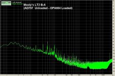
The devices were very different. Opamp A was an OPA604 and Opamp B the AD797. I think its fair to say that the images of the distortion showed the AD797 to be far superior when driving the low impedance load with the distortion remaining essentially off the radar.
Mooly, can you please post your AD797 test circuit?
Thanks...
by seeing if the obvious huge difference in distortion was detectable in any way.
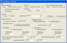
Here are the differences btn the four files.
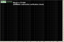
(Audio DiffMaker SW does the time alignment, gain alignment, compensation for sample rate drift and then subtracts one file from the other. Resulting wave files have very low sound level. Turn up the volume during playback).
Mooly’s LT2 B-B
https://www.dropbox.com/s/c6vgt28cstpvt9u/Mooly%E2%80%99s%20LT2%20B-B%20%28DiffMaker%20subtraction%20verification%20check%29.wav?dl=0
Mooly’s LT2 B-A
https://www.dropbox.com/s/smkt2100ma6f5u1/Mooly%E2%80%99s%20LT2%20B-A%20%28AD797%20%20Unloaded%20-%20OPA604%20Loaded%29.wav?dl=0
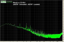
Mooly’s LT2 B-C
https://www.dropbox.com/s/2fvzuvfgnulp95b/Mooly%E2%80%99s%20LT2%20B-C%20%28AD797%20%20Unloaded%20-%20AD797%20%20Loaded%29.wav?dl=0
Mooly’s LT2 B-D
https://www.dropbox.com/s/nrk5iiq2dy4t3t7/Mooly%E2%80%99s%20LT2%20B-D%20%28AD797%20%20Unloaded%20-%20OPA604%20Unloaded%29.wav?dl=0
George
Attachments
-
 Audio DiffMaker.JPG73.3 KB · Views: 238
 -
 Mooly’s LT2 B-B (DiffMaker subtraction verification check).JPG124.4 KB · Views: 242
 -
 Mooly’s LT2 B-A (AD797 Unloaded - OPA604 Loaded).JPG143.8 KB · Views: 233
 -
 Mooly’s LT2 B-C (AD797 Unloaded - AD797 Loaded).JPG142.4 KB · Views: 237
 -
 Mooly’s LT2 B-D (AD797 Unloaded - OPA604 Unloaded).JPG142.8 KB · Views: 233
Sorry Mooly, Impossible for me to download your files: I'm a fresh (2Days) emigrate in Portugal, and i have no Internet in my new house for the moment.
Just my French phone card, limited in datas.
About Feedback, distortion, open loop bandwidth and all that sort of things, I had no time to read all the answers. Did anyone explained that, when the open loop bandwidth is limited, The phase begin to turn at a lower frequency. The feedback principle is to subtract the output signal from the input one. If they are not in phase, the subtraction is not accurate.
Now, are the open loop distortion harmonics affected by those phase turns as the signal is? I believe all depend of the structure of the IC, where they are generated, where in the IC is the stage witch has the most important part on the phase behavior etc...
Not a rethink, just trying to present my findings in a way to make sense - which ending up not making sense !!Frank (I hope you don't mind me putting this here
Quote,
"Better opamp ... Poorer
LT1:
Normal 4 3
Loaded 1 2
LT2:
Normal A B
Loaded C D
And then a rethink which randomised things somewhat,
Quote,
"better" opamp; i.e. 4,1 and A,C. Thus, the "poorer" unit was 3,2 and B,D"
I'll try again ...
Ltest1 = Better Loaded.
Ltest2 = Poorer Loaded.
Ltest3 = Poorer Unloaded.
Ltest4 = Better Unloaded.
LtestA = Better Unloaded.
LtestB = Poorer Unloaded.
LtestC = Better Loaded.
LtestD = Poorer Loaded.
These are all identical results, just presented in different formats!
The LT1 samples for me were very distinctively different, I had a harder time with LT2, my setup was a bit dodgy, and the piano was provoking the speakers to misbehave, I'm getting some rubbing noises at times.
Interestingly, the OPA604, unloaded, for my setup, presented SY's recording to best advantage, by quite a margin - purely a coincidence, experimental error, or ... ?
Edit: To my ears, what I called the "better" samples made the tonal qualities of what I was hearing more distinctive, allowed me to discriminate more easily the details, in sound terms, of what was happening. In particular, the individual qualities of the voice, and the guitar, in LT1 were separated, were distinct sound elements; in the "poorer" these tonal qualities were homogenised, as if they had gone through a sound blender so to speak.
Last edited:
In the context of an op-amp input device this stuff is mostly marketing blather and basically wrong. An LTP of FET's or bi-polars does not predominantly produce seconds, this is EE101.
No it is not EE101. The first course in most places covers the actual basics like Ohms law, Thevenin & Norton, components (resistors capacitors transistors and sometimes inductors), circuit theory and frequency/time results. It has a lot of stuff that seems overlooked or avoided here, like actually doing the math for a simple circuit analysis.
In the distant past, I found that -with book shelf speakers of modest distortion - I lost the ability to detect differences when the source thd was at or below 0.1%..... something of about <.05% would be transparent to me. Now I have lower distortion speakers etc so I should try this again. Here and now with this test from Mooly, the distortion is lower than 0.1% and most hear a difference. It just takes experience to know for sure which sound is more accurate.... doesnt matter to me what someone likes but that they hear a difference at these low thd levels. Now, how low do we have to go to Not be able to hear any difference?
With the new undetectable thd level known, we need amps with maybe 10X lower to assure accumulated distortion in the entire system wont be heard. I figured at least -100dB or better.
THx-RNMarsh
With the new undetectable thd level known, we need amps with maybe 10X lower to assure accumulated distortion in the entire system wont be heard. I figured at least -100dB or better.
THx-RNMarsh
Last edited:
Haven't looked at George's Diffmaker files as yet, but doing my own, manual version thereof, with Audacity, again get interesting results.
I used samples A and D, which were the most different for me - to get precise alignment I needed to oversample to 96K, and then shift one version; this then aligned all the high energy, over 10K spectra to single sample precision.
After inverting, and subtracting that left me with a very messy difference file, which again was only of the order of 40dB down from the amplitude of the source waveform - i.e. would be quite audible, as distortion. What about precisely adjusting the amplitude to match, you say? The answer depends upon what waveform of "messiness" you want in the difference file - adjust the amplitude minutely to cancel a biggest, obvious bleedthrough of the original waveform; and what you get is just as messy, but different. So, which is the "right" difference file - pick a number between 1 and ... ??
There are also anomalies almost like step variations in the difference waveform at odd points, noted also in the test done some days ago.
Last edited:
- Status
- Not open for further replies.
- Home
- Member Areas
- The Lounge
- John Curl's Blowtorch preamplifier part II