Mooly's test was good. Despite gross overloading, telling the diff between the two was still not a slam dunk, and worse, no one could really identify the heavily loaded one beyond 50/50 chance.
Let's repeat the experiment, but with a very well recorded piece of music.
I'd love to see this methodology expanded to compared high end equipment against a reference. This approach has merit as a subjectivist ball buster.
Let's repeat the experiment, but with a very well recorded piece of music.
I'd love to see this methodology expanded to compared high end equipment against a reference. This approach has merit as a subjectivist ball buster.
no one could really identify the heavily loaded one beyond 50/50 chance.
Not really true for me. I did... and, I wasnt afraid to say confidently which was which before results were told... because I knew from experience.
But without a rigorous statistical test, I could say, not proven beyond a shadow of others doubt.
There are no golden ears.... just learning correlations for >>10,000 hours.
THx-RNMarsh
Last edited:
It would be so easy to put up a set of files of say two 20dB line amps with the ONLY difference that one uses Dale 1% resistors and the other uses naked Vishays. (I'll pay for the Vishays if you want). This is where the discussion wanders off to all too often. Same goes for coupling capacitors, but I'm not paying $400 for a bespoke teflon cap.")
I did such test here, a year ago.
http://www.diyaudio.com/forums/ever...odenstein-mkt-listening-test-preparation.html
Mundorf x Roedenstein as coupling caps.
Right you are, Dejan, it is useless to test an opamp with 100 ohm load. It should have been something like AD811 or LM6171 to do the job. Try LM6171, Karl.
That's one I've never used (and haven't got) I'm afraid.
No, it is NOT. That's the point. You are given just 2 choices and told there is a difference. Bad test, proves little to nothing. (Sorry Mooly).
Appreciate the honesty
Its very difficult devising tests to please everyone. The biggest problem is that it can end up to much work for the listener. Well, I think Mooly's intent was to say, "OK, everyone is talking about loading ... well, can we hear a difference if that is altered?" Simple as that. The answer is, "Yes", so then we move on ...
That's what started it all, yes.
Mooly what's the inhibition, put up two files with a single wire cut in half and connected in both directions in the input as the only difference.
N-S or E-W alignment for that
An interesting alternative, which perhaps Mooly is considering, is deliberately loading to the point where distortion is trivially obvious, say 40R. Then do a series of tests where the load is doubled each run, to well past a value that's an issue. Test is then to have people rank them in order.
I like that idea. If he could show the distortion spectrum (or we do it for him) that would be even better.
But Mooly needs to be careful not to give any clues!
That has been done with this latest test. (Spectrum, not clues. I hope)
Mooly's test was good. Despite gross overloading, telling the diff between the two was still not a slam dunk, and worse, no one could really identify the heavily loaded one beyond 50/50 chance.
Let's repeat the experiment, but with a very well recorded piece of music.
I'd love to see this methodology expanded to compared high end equipment against a reference. This approach has merit as a subjectivist ball buster.
The new test has two music pieces. File size might be an issue for some though. One piece was kindly provided by SY (thanks
) and its proved a tough one to get the best from it. Originally a 24/96 master, there is one very brief section that's a killer with dynamics. I suspect my ADC is the limiting factor here. Non the less its a cracker. Lots of detail, very quiet for the most part. The other files are shorter and a different piece.This is just a quick sampler of the differences between loaded and unloaded and one opamp type against the other. The differences are real and obvious... but are they when listened too.
Attachments
This listening test is similar to the earlier one but has the added bonus of two high quality devices under test. These are also single opamps and not duals.
OK, here we go
Firstly, I don't want to discourage anyone from taking part and so this test can be as simple, or for those that like analysing files, as complex as you wish, but I also want it to be as interesting and fun as possible. All things considered, its easy to get a perfect Foobar score simply by adding a spoiler/s to the tracks and picking those out. I hope if you listen, you do so as "just a piece of music" and base your comments accordingly. If we are to learn from this then its important just to be honest and report what you hear.
The circuit details are similar to the earlier one with the exception of an added input filter (a 470pf cap to ground after the 2k2 input resistor) and a 22pf cap across the feedback resistor. This was needed for one device and so it was only fair to keep the circuits identical for both. These small value caps were high quality polystyrenes. Each opamp was decoupled at the supply pins with a 100uf quality commercial grade cap. The PSU was a fully charged 12 volt 7Ah V.R.L.A. battery.
The source for all these files was a Marantz Pearl-Lite SACD player. This player is "opamp less" and uses discrete FET/Bjt stages.
So the files... and they are really easy to use, are complete in themselves and are "zipped".
LT1
LT2
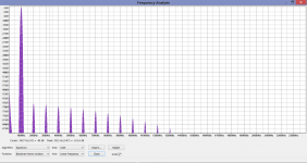
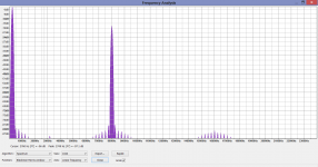
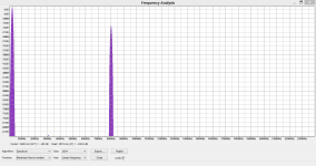
The downloads. Folder LT1 and LT2 both contains spectra images but beware of the total download sizes. LT1 is 143mb and LT2 is 32mb. For those on a limited allowance or slow connection I would advise just using folder 2. The picture names (A1, A2 etc) relate to one device and B1, B2 etc to the other. Each folder has an identical set of images. Its obvious that one device produces way more distortion than the other and its not giving anything away to say that the higher levels are when loaded.
The audio files within each folder are random in order and there is one each for each opamp, both loaded and unloaded. So four audio files in each folder.
The big question... can you identify or have a preference for one any one file in each set ?
OK, here we go
Firstly, I don't want to discourage anyone from taking part and so this test can be as simple, or for those that like analysing files, as complex as you wish, but I also want it to be as interesting and fun as possible. All things considered, its easy to get a perfect Foobar score simply by adding a spoiler/s to the tracks and picking those out. I hope if you listen, you do so as "just a piece of music" and base your comments accordingly. If we are to learn from this then its important just to be honest and report what you hear.
The circuit details are similar to the earlier one with the exception of an added input filter (a 470pf cap to ground after the 2k2 input resistor) and a 22pf cap across the feedback resistor. This was needed for one device and so it was only fair to keep the circuits identical for both. These small value caps were high quality polystyrenes. Each opamp was decoupled at the supply pins with a 100uf quality commercial grade cap. The PSU was a fully charged 12 volt 7Ah V.R.L.A. battery.
The source for all these files was a Marantz Pearl-Lite SACD player. This player is "opamp less" and uses discrete FET/Bjt stages.
So the files... and they are really easy to use, are complete in themselves and are "zipped".
LT1
LT2
The downloads. Folder LT1 and LT2 both contains spectra images but beware of the total download sizes. LT1 is 143mb and LT2 is 32mb. For those on a limited allowance or slow connection I would advise just using folder 2. The picture names (A1, A2 etc) relate to one device and B1, B2 etc to the other. Each folder has an identical set of images. Its obvious that one device produces way more distortion than the other and its not giving anything away to say that the higher levels are when loaded.
The audio files within each folder are random in order and there is one each for each opamp, both loaded and unloaded. So four audio files in each folder.
The big question... can you identify or have a preference for one any one file in each set ?
Right
I can tell when it's time to exchange the filter for the fridge's water dispenser/icemaker, does that count ?
(Trouble with DIY is that most handiwork ends up looking like a gathering of 2nd hand heatsinks, used transformers, nos electrolytics, and high-solder PCB's with repair work. If the designer is lucky, held in a wooden casket, and ready for burial)
No using 60V parts at 200V makes it sound extra special and creates new physics to boot. That is real fashion audio.
The mil hybrid place I worked at, I had to screen some devices on wafer to voltages well above manu's spec. 40 volt parts were tested to 60 volts on a regular basis, and used. On occasion, I'd find some that would not like it when they were run active at low voltage and then the collector slewed to 60 volts. A strange combo of early effect, emitter geometry, and slew rate. Wiped the devices during BVce (sus).
That's easy...the whachamacallit number thingy in my fridge says "zero"I can tell when it's time to exchange the filter for the fridge's water dispenser/icemaker, does that count ?
(Trouble with DIY is that most handiwork ends up looking like a gathering of 2nd hand heatsinks, used transformers, nos electrolytics, and high-solder PCB's with repair work. If the designer is lucky, held in a wooden casket, and ready for burial)
Why is that trouble??
What is nos?
jn
the whachamacallit
I assumed that was the temperature indicator.
(new old stock, now off spec, or a cap on life-support)
Attachments

.
-140 dB THD+N is a slight problem, but it can be done.
S
He did say 200kHz so being generous and say you only look at the first two harmonics that's a 600kHz noise BW. -140dB at 7V rms in 600kHz is about .9nV/rt-Hz so now the real part of the impedance of all the frequency generating components must be <50 Ohms. For fixed frequency oscillators I think only Baxendall's passive L/C post filtering could do this though I shudder to think of doing it at 50 Ohm's
Mine has digital readout of freezer temp, fridge temp, and percentage life remaining in the filter.I assumed that was the temperature indicator.
Ah, so that explains the T-shirt I was given for my birthday..(new old stock, now off spec, or a cap on life-support)
jn
Mine has digital readout of freezer temp, fridge temp, and percentage life remaining in the filter.
(should have known you're not part of the GTB)
This is just a quick sampler of the differences between loaded and unloaded and one opamp type against the other. The differences are real and obvious... but are they when listened too.
Karl, what was the signal amplitude.
Thanks Mooly for your harmonic and IM measurement. Was that a 4562? I just want to know for sure. I have found the same sort of measurement with other IC's, so it is consistent with prediction.
The first one from a couple of days back was a 4562. These are somewhat different... you'll find out soon enough. Have you given any a listen ?
- Status
- Not open for further replies.
- Home
- Member Areas
- The Lounge
- John Curl's Blowtorch preamplifier part II