Yes, they have forgotten. I used to use CRT's as part of the tour explanation about charged particles moving in a magnetic field and accelerating at a right angle to both via the right hand rule.. Now, they look at me bewildered, wondering what a tv "tube" is.Thanks for the information and confirmation of an unshielded magnetic speaker magnets flux field. I wonder if people have sort of forgotten about what a large magnet from a speaker can do since most people have flat screen TV's and computer monitors these days, I haven't placed a large magnet near a flat screen TV or monitors to see if there is still some kind of effect.
sigh..
jn
Hi Scott,
A few years ago I asked the question on this forum "anyone know the frequency response of air" none of the answers at that time indicated to me that there was a clear understanding of this.
Does your comment above mean that this is well understood by yourself ?
If so, could you explain some more ?
It depends on the temperature and humidity. There is a classic chart of it easily found and of course it is wrong. There is a newer IEC standard calculation that is much better. I did find a website that calculated it, but have since lost the info.
The first time I tried to get good measurements I realized the books all used dry lab results. It turns out that there is this thing called wind, that really screws up the ability to make the measurements accurately. But HF loss at 100 feet can be 20 db.
Since quite a long time i have an idea that could reduce distortion in loudspeakers.
Second harmonic comes from asymmetries.
I learned from Klippel that this can also be seen as a DC shift.
My idea is to make a power amp that has adjustable DC Offset.
That offset could be used to partial cancel second harmonic.
Maybe not under all conditions but it is worth a try.
The asymmetries in a sealed box are also affected by changes in atmospheric pressure. Although long term there is enough leakage that there is no permanent displacement.
As I am sure you are aware voice coil alignment is still done mostly by hand in pro woofers and thus varies a bit.
It depends on the temperature and humidity. There is a classic chart of it easily found and of course it is wrong. There is a newer IEC standard calculation that is much better. I did find a website that calculated it, but have since lost the info.
The first time I tried to get good measurements I realized the books all used dry lab results. It turns out that there is this thing called wind, that really screws up the ability to make the measurements accurately. But HF loss at 100 feet can be 20 db.
Thx Ed, I find this HF 20db down @ 100 feet very interesting.
I have noticed myself the big difference in sound according to where one is positioned in the concert hall and I feel sure that different people will have different preferences about where they sit. "Prime" seats are often 30 - 40 feet from the front of the orchestra.
So many live concert goers will be used to hearing classical music with the treble considerably attenuated.
This makes me feel much more open to the idea of rolling off the treble to some extent if the listener prefers.
Some people like sitting close to the front - some people like sitting further back.
Some people like flat 20- 20khz - some people like the treble rolled off.
Just a matter of preference.
Since quite a long time i have an idea that could reduce distortion in loudspeakers.
Second harmonic comes from asymmetries.
I learned from Klippel that this can also be seen as a DC shift.
My idea is to make a power amp that has adjustable DC Offset.
That offset could be used to partial cancel second harmonic.
Maybe not under all conditions but it is worth a try.
This is in fact being done by at least one person. he adjusts the dc to the driver to get the VC centered and lowest distortion. And, he checks and adjusts it depending on weather/pressure/humidity etc in the room. I think his cones were paper based. He lives in the San Fransisco bay area.... Stanford, actually. Brian Elliot. Retired IBM/HP.
I heard his system in which he did the DC adjustment and his system sounds wonderful (because of this and many other things he does).
As for other common source of 2H, the cone to surround interface is often another problem of QC; If the cone is cut too small - even a very small amount - the cone wont be pushing at the surround and flexing at the surround 'corner' will occur which leads to higher distortion. So take a real close look at the cone-surround interface before buying.
View attachment cone-surround interface.pdf
THx-RNMarsh
Last edited:
Richard,
If you would ever play with the speakers I sent you you would find that you could play with the dc offset all you want and it would do virtually nothing as the voicecoil is in such a long gap with even magnetic field you would accomplish nothing. This is only a problem with either an equal hung voicecoil or an overhung voicecoil in an asymmetric magnetic field.
ps. What Joachim is suggesting with driver design was that the actual physical conditions causing the 2nd harmonic are caused by an asymmetric suspension, there are differences in the restorative forces caused by the surround, not as much the spider due to the shape of the surround. You can imagine the spring loading changes of a simple 1/2 roll surround vs a more complex shape that would linearize this restorative force.
Last edited:
Richard,
If you would ever play with the speakers I sent you you would find that you could play with the dc offset all you want and it would do virtually nothing as the voicecoil is in such a long gap with even magnetic field you would accomplish nothing. This is only a problem with either an equal hung voicecoil or an overhung voicecoil in an asymmetric magnetic field.
ps. What Joachim is suggesting with driver design was that the actual physical conditions causing the 2nd harmonic are caused by an asymmetric suspension, there are differences in the restorative forces caused by the surround, not as much the spider due to the shape of the surround. You can imagine the spring loading changes of a simple 1/2 roll surround vs a more complex shape that would linearize this restorative force.
Thanks for the clarification/qualification.
I wasnt commenting on the cause but that a dc force can help get lower distortion. Also how the surround is attached IS a cause... see above comment and illustration.
Thx-RNMarsh
Last edited:
Yes, you don't want to add a cantilever to the 1/2 round, that would add another non linearity to an already problematic situation. One of the problems is that using other than a simple roll surround then adds additional acoustic factors such as additional cavities around the outside of the cone and also other phase relationships of the moving surfaces. It is a very complex situation when you look at all the interactions of the cone and surround both mechanically and acoustically. I would love to be able to spend a day with Joachim and his Kipple system just looking at the different surround actions and surround shapes.
Have you tried a zobel at the speaker end to match the cable?
Yes, and in a few other cases that was indeed the problem. Not this time, though.
I think I've tracked it down to a CCS that's resonating at 10MHz. Oddly enough when I compensate it with the simulated solution, I get a weird 100KHz resonance that I can't reproduce in the simulator. I suppose that is yet another trimmer to add.
To test my theory of the BC5xx having low Ym at RF, I've realized I can use the DC offset function on my FG504 to bias a transistor into conduction while at the same time injecting a signal to measure Ym.
Current Drive
Richard,
At this point I cannot stretch any further, I am in the middle of launching several products and will be buried until early next year.
I do think it is an exciting project, one which may have marginal market appeal due to the fact that the approach has to be an integrated amp and speaker...and as you know better than I, to do this with any substantial quality and power makes the whole package $$. This is why I pinpointed the mobile sound market: the speakers were made by the same companies as the amps.
As an interesting anecdote, when I was flying around demoing the idea, I knew I couldn't lug a big amp and pair of speakers, so I took the transconductance circuit modified to allow manual phase and amplitude nulling, and a little test circuit I designed to indicate proper null. This way I could get to a prospective customer's place and use his speakers and amps. It was time consuming, but I still have a back...
Cheers!
Howie
Howard Hoyt
CE - WXYC-FM 89.3
UNC Chapel Hill, NC
www.wxyc.org
Well that sure does suck big time.Wanna start it up again? Using my TC Sounds (18 incher)? Dual 2 Ohm coils.
THx-RNMarsh
Richard,
At this point I cannot stretch any further, I am in the middle of launching several products and will be buried until early next year.
I do think it is an exciting project, one which may have marginal market appeal due to the fact that the approach has to be an integrated amp and speaker...and as you know better than I, to do this with any substantial quality and power makes the whole package $$. This is why I pinpointed the mobile sound market: the speakers were made by the same companies as the amps.
As an interesting anecdote, when I was flying around demoing the idea, I knew I couldn't lug a big amp and pair of speakers, so I took the transconductance circuit modified to allow manual phase and amplitude nulling, and a little test circuit I designed to indicate proper null. This way I could get to a prospective customer's place and use his speakers and amps. It was time consuming, but I still have a back...
Cheers!
Howie
Howard Hoyt
CE - WXYC-FM 89.3
UNC Chapel Hill, NC
www.wxyc.org
Mic phase
Wow, good insight...Although I have used both dynamic and condenser mics in the same recording situation with little destructive combining (not directly side-by-side, though, in which situation any interaction would be maximized). Are you sure their current phase relative to diaphragm position is different? The maximum speed of the diaphragm is at the middle of it's excursion, so the greatest current peak of a dynamic mic would be at that point as well. There would be the greatest delta V/T for a condenser mic at that point, so would it not also have the greatest current as well? It seems as if, at the end of excursion for either, the current is at minima and voltage at maxima.
As regards to speakers, it seems like the situation would be similar. When researching the current drive I didn't worry about absolute phase, as it seemed like driving a dynamic driver with current established the correct phase as opposed to voltage drive. Hmmm, my experiments in this were 25 years ago, I need to read Esa's book again...darn memory cells...Anyone else have experience with this?
Howie
Howard Hoyt
CE - WXYC-FM 89.3
UNC Chapel Hill, NC
www.wxyc.,org
Here is a question, relevant to both speakers and microphones. Many years ago I read that mixing an dynamic mike with a condenser mike on the same instrument was problematic because of the phase relationship of the pressure wave to the electrical output. A dynamic mike has its peak out out at the fastest changing part of the waveform- the zero crossing. The condenser at the peak of the pressure wave, 90 degrees different. I have never verified this, no need to, but it sounds reasonable.
Could the same be true for voltage and current drive of a speaker? And in the current amplifier, is the peak current at the peak of the input voltage wave? The few experiments I have tried in the past had a good phase/amplitude correlation of the current driving a speaker (dynamic and electrostatic) and the voltage wave from a condenser mike in front of the speaker.
This could lead to more angst than getting absolute phase of the playback right. You need an electrostatic speaker for recordings made with condenser mikes and dynamic speakers for dynamic mikes. Or is it the other way? What about carbon mikes?
Wow, good insight...Although I have used both dynamic and condenser mics in the same recording situation with little destructive combining (not directly side-by-side, though, in which situation any interaction would be maximized). Are you sure their current phase relative to diaphragm position is different? The maximum speed of the diaphragm is at the middle of it's excursion, so the greatest current peak of a dynamic mic would be at that point as well. There would be the greatest delta V/T for a condenser mic at that point, so would it not also have the greatest current as well? It seems as if, at the end of excursion for either, the current is at minima and voltage at maxima.
As regards to speakers, it seems like the situation would be similar. When researching the current drive I didn't worry about absolute phase, as it seemed like driving a dynamic driver with current established the correct phase as opposed to voltage drive. Hmmm, my experiments in this were 25 years ago, I need to read Esa's book again...darn memory cells...Anyone else have experience with this?
Howie
Howard Hoyt
CE - WXYC-FM 89.3
UNC Chapel Hill, NC
www.wxyc.,org
Last edited:
Move to Georgia. Building can be had cheap and there is a big airport here . Madisound where I found the 550 price . P.S no taxes on retirement income and we have lots of water and clean air now .550? Guess, I should get one of them.
I also need to invest in a large test equipment warehouse.
-RM
Hi Scott,
A few years ago I asked the question on this forum "anyone know the frequency response of air" none of the answers at that time indicated to me that there was a clear understanding of this.
Does your comment above mean that this is well understood by yourself ?
If so, could you explain some more ?
That's a different question, I was just commenting on the basic particle displacement relationship to SPL.
There would be the greatest delta V/T for a condenser mic at that point, so would it not also have the greatest current as well? It seems as if, at the end of excursion for either, the current is at minima and voltage at maxima.
[/SIZE]
A condensor mic can be used with either voltage or current sensing (I need to think about it a while) Goran any comments? It's interesting that I never came across this issue in all the B&K and Schoeps tech literature. I do know the distortion is different in the two modes.
Yes, and in a few other cases that was indeed the problem. Not this time, though.
I think I've tracked it down to a CCS that's resonating at 10MHz. Oddly enough when I compensate it with the simulated solution, I get a weird 100KHz resonance that I can't reproduce in the simulator. I suppose that is yet another trimmer to add.
If you have enough headroom, simply adding resistor in series with the CCS might fix the problem.
Move to Georgia. Building can be had cheap and there is a big airport here . Madisound where I found the 550 price . P.S no taxes on retirement income and we have lots of water and clean air now .
NOW I find out !
I just bought a place in Bangkok, Thailand.... no property taxes.... unlike california. Low cost everything and healthy food (no GMO) always fresh and ripe. Some times too much water and can have bad air but getting better.... and it has ocean wind to blow it to the others inland. Going there in 2 weeks for awhile and play as a retired person. But, I will look into Madisound... Thx for the info.
-Richard Marsh
A condensor mic can be used with either voltage or current sensing (I need to think about it a while) Goran any comments? It's interesting that I never came across this issue in all the B&K and Schoeps tech literature. I do know the distortion is different in the two modes.
I'm not sure why the distortion would be different. I know the current mode is part of reciprocity calibration, something I still have trouble fully comprehending. I have found that the B&K preamps seem to limit the distortion potential. I have some HP preamps that measure significantly lower distortion than my B&K preamps.
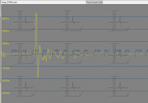
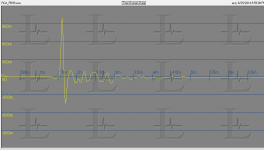
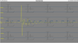
I found this looking for some info on the difference between dynamic and condensor mikes: Microphone Impulse Response Project and he has impulse responses for a lot of microphones. They are all wave files so they need to be imported into something to see. I plotted the wave files of a ribbon, condenser and dynamic mikes to see if there is something obvious. Since there is not quite enough info to derive all the information like distance to the source etc. but still a start on the efforts. I may try to import the files and do transforms. That's for later.
Some more reading https://www.neumann.com/download.php?download=lect0048.PDF Alternate self promotion Impulse Response
There is a lot on impulse response on the web and a lot of work using captured impulse responses of spaces to modify sounds. Much to explore.
Attachments
As I am technically/electronically challenged, hope no one laughs at probably a silly idea but ...Thanks for the clarification/qualification.
I wasnt commenting on the cause but that a dc force can help get lower distortion. Also how the surround is attached IS a cause... see above comment and illustration.
Thx-RNMarsh
Speaker Driver Limitations
...can we do away with speaker surround llike in post #7 above ? Will that concept work at all ?
Thanks and regards.
- Status
- Not open for further replies.
- Home
- Member Areas
- The Lounge
- John Curl's Blowtorch preamplifier part II