Great overview. I have been aware of those ideas but did not think them too practical for consumer products.Demian,
You may want to put the inductor on the AC side of the bridge. For a complete list of passive current shaping rectifier circuits see:
http://www.sdaengineering.com/mepcon10/papers/154.pdf
Please note that the best looking results of the circuit in 3.1.5 are not practical to achieve. The parallel traps will draw the harmonic currents of any non-linear load connected to the mains. Proper dimensioning for power dissipation thus become a big question mark. The solution has its merits in closed systems like the 400Hz power distribution of avionics systems for instance.
Giorgio
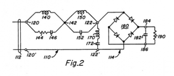
I have been using a different solution for years, here: Patent US5251120 - Harmonic noise isolation and power factor correction network - Google Patents that has shown amazing results. It has proven really difficult to make due to the magnetics. If you follow what it does its similar to the traps but in a different way. In operation the voltage waveform into the diodes is square and the current waveform from the line is really clean when optimized. The peak currents into the diodes are lower than when directly connected, almost like a choke input supply.
Attachments
The trouble with any transformer is that it always has its own sonic signature, even when it is not in saturation. Isolating transformers pass this signature on to everything after them.
During the last 13 years plus, I have never heard a power line filter using a transformer which did not, more or less subtly, change the sound of my system. This is why I stay away from them.
Presumably you mean changes in the sound for the worse - I wonder why that would be . . . .
Anyway, as it happens I have some isolation trannies in the attic so I can check out this idea quickly & easily and draw my own conclusions.
if you would take a 'tiny' transformer with no choke, instead of a big transformer and an AC side choke, would you not get the same effect?
Jan,
For a "tiny" transformer to achieve the same effect of a big transformer and AC side choke the leakage inductance must be so large that the accompanying radiated field would make the exercise useless.
Rather, I would use a "tiny" capacitor and bite the bullet on the power dissipation of the downstream regulator.
Look at it this way: instead of seeking for the lowest voltage ripple amplitude alone, you design the system for low voltage AND current ripple amplitude and least harmonics in the voltage AND current waveforms.
The voltage regulator can attenuate any reasonable voltage ripple if its frequency content is narrow band. This is where you want your switches (diodes) to be as low noise as possible. The goal is to limit the noise to the fundamental frequency and very few harmonics. Diodes are noisy at much higher frequencies that are not correlated with the mains frequency.
Giorgio
I have found that any L in series with the primary of a power transformer is not good sounding in my system. A cap across the line is good. I want any harmonics generated from the power supply to go back to the point of lowest Z which is the big power companies transformer on the pole that feeds my house. I think it was in Ott's book that he said that noise will seek the lowest impedance.
I want any harmonics generated from the power supply to go back to the point of lowest Z which is the big power companies transformer on the pole that feeds my house
Rick,
Harmonic currents generated by a capacitor input rectifier are conducted on the mains line and propagated to other equipment connected to the same network. It is this effect that produces interferences and "bad sound".
The mains line has finite, non-zero, impedance. When current is taken in short pulses in correspondence with the voltage peaks, the net effect is a voltage drop equal to the current pulse multiplied by the mains line impedance. This results in a distorted VOLTAGE waveform. The same voltage waveform that is distributed throughout your house down to the big transformer mounted on the pole, etc.
This is the reason why the rectifier TOPOLOGY is important.
Giorgio
I have been using a different solution for years
Demian,
If you designed that into anything other than a military program backed by BIG $$$ ...you are my hero!

Hats off!
Giorgio
Well, I added a 100VA line isolation transformer upstream of my existing mains filter that feeds to my DAC and in this case, using purely subjective assessment, it sounds like it is removing more problems than it is adding - very fine detail is more defined - I like it and will experiment further tomorrow but I think it will be staying in some form or other.
I suspect adding 250VA versions to each of my amps my not be so great but as I have enough to do the entire system I will try it and see.
Thanks dvv, your description of how horrible the mains looks on a scope inspired me to try this it seems to work well for me.
I suspect adding 250VA versions to each of my amps my not be so great but as I have enough to do the entire system I will try it and see.
Thanks dvv, your description of how horrible the mains looks on a scope inspired me to try this it seems to work well for me.
So you think it is more than just differing PSNR ratios on different designs ?
Yes I think it is more than the noise. It has been some time since I have made measurements of the line with rectifier changes. I need to go back and look at the data and measure the SIC parts. In the case were they sounded worse in the bass it was a toroidal feeding the SIC parts followed by a CRC then cap multiplier and active regulation. The circuit was fet with maybe 10 dB feedback.
I only need more hours in a day for all this stuff. There are many permutations to measure and listen to.
We might want to talk about the value of a capacitance multiplier and if it actually makes things better.
Dick,
I have a bone to pick with you. Before when discussng measuring diode noise we compared the current probes we both own. You failed to show the article on rolling your own.
Well I spent two hours this afternoon building a wide band low noise 20db preamp, a current probe as mentioned in the LT ap note and used a small tuning slug core to build a small current probe as shown in your article
Well the LT style probe did show current when inserted into a test loop. Nothing worth looking at in the actual circuit. Then I ran a diode lead through the current transformer.
Using one channel for the probe and the other looking at the transformer secondary voltage to get a trigger, I got the best images of current through a diode by an amazing margin!
I see baseline noise until the diode conducts. Then I see the charging current although due to LF band limits it is probably limited a bit. I also see the line noise ride in while the diode is conducting. I clearly see the charging tail change depending on filter capacitor size. And for the first time I see a beautiful turn off spike. I can zoom in on it and even watch how well the various damping methods work. If I get a chance tomorrow I will post some images.
So now I have to pick up an assortment of cores and make and calibrate a series of probes. So not only did you hold out on a great method, you have created even more work for me.
ES
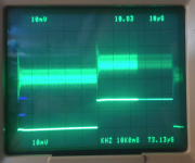
Here is the same current using two current probes. The lower trace is a Tek AM503 ($500+) the upper trace is Quantasylum QA190 QA190 Differential Probe which gives both a current probe (better suited to higher currents) and a differential voltage probe good for 150V for $79. They are looking at 10KHz at 4V into 50 Ohms or 80 mA P-P. The QA190 can work with DIY probes I suspect and that may prove useful. While its noisy at the 80 mA level you can see the waveform. This probe is scaled for 10A/V.
I have an assortment of current probes and they are all very useful for looking at switching waveforms. A few mag field probes are also very useful to see how far the disturbance goes.
I have an assortment of current probes and they are all very useful for looking at switching waveforms. A few mag field probes are also very useful to see how far the disturbance goes.
Attachments
Demian,
If you designed that into anything other than a military program backed by BIG $$$ ...you are my hero!
Hats off!
Giorgio
I built a version into some preamp supplies. Those were very over the top with an 8Lb (4KG) transformer for 15W, custom designed for highest isolation and running a much reduced gauss. And I built a handful scaled to about a 400W load as products to sell. They proved to be a real challenge to get the magnetics right. Most shops are oblivious to buzz and gapped cores will tend to buzz. One shop wanted $20K to build a set of prototypes. I passed on them. They were not conversant with spice or magnetic modelling but were pretty sharp on magamps. I'm still shopping.
The capacitor doesn't absorb the noise, it just provides a path for it. The resistor dissipates the noise. A reactive element cannot dissipate power,
only a resistive element.
I didn't expect anyone to use such a precise definition of 'absorb'.
Say we put a resistor in series with the cap, expecting it to 'absorb' the diode glitches. Paradoxically, it resists the glitches, prevents them from being shorted through the cap, and sends them on to the transformer.
So, while meaning well, I think you are actually working against your original intentions.
Presumably you mean changes in the sound for the worse - I wonder why that would be . . . .
Anyway, as it happens I have some isolation trannies in the attic so I can check out this idea quickly & easily and draw my own conclusions.
Not necessarily for the worse, perhaps sometimes just different. The rest is perosnal taste.
Good that you have them, nothing beats personal experience.
Well, I added a 100VA line isolation transformer upstream of my existing mains filter that feeds to my DAC and in this case, using purely subjective assessment, it sounds like it is removing more problems than it is adding - very fine detail is more defined - I like it and will experiment further tomorrow but I think it will be staying in some form or other.
I suspect adding 250VA versions to each of my amps my not be so great but as I have enough to do the entire system I will try it and see.
Thanks dvv, your description of how horrible the mains looks on a scope inspired me to try this it seems to work well for me.
Not at all, Mike, I have also been helped by people from this forum quite a bit. Anyway, the key point is you are gathering your own experience. Mine is nice, but your own is better.
As for the scope spectrum, it is usually rather depressing and is there for all to see. As I said, it does vary from one place to another.
Great overview. I have been aware of those ideas but did not think them too practical for consumer products.
I have been using a different solution for years, here: Patent US5251120 - Harmonic noise isolation and power factor correction network - Google Patents that has shown amazing results. It has proven really difficult to make due to the magnetics. If you follow what it does its similar to the traps but in a different way. In operation the voltage waveform into the diodes is square and the current waveform from the line is really clean when optimized. The peak currents into the diodes are lower than when directly connected, almost like a choke input supply.
Demian,
If you transpose the series of parallel LC into a parallel group of series LC you get better results - sonically, also.
[I know... cause I have a patent on it]
THx-RNMarsh
Demian,
If you transpose the series of parallel LC into a parallel group of series LC you get better results - sonically, also.
[I know... cause I have a patent on it]
THx-RNMarsh
Doesn't work. Its not a filter. (I checked to be sure and the output is 30V instead of 140V) The USPTO had trouble understanding it as well. Build a spice model and study how it works. Hint: The series networks are called reflectors and the shunt is called a pump.
Richard,
It is true that a parallel resonant "harmonic trap" filter has better performances than the series arrangement of the same. It is however more limited in scope and, IMHO, probably not the best approach for an audio system. I try to explain...
If you consider a preamp + amp system, the harmonic trap filter is a suitable solution for the preamp only. The power amp cannot use the same approach unless it is of very limited power. Ideally, you could use an active PFC with all of its shortcomings. In practice, only a few power amp for the consumer market are PF corrected (Halcro and Nagra comes to mind, pro audio is different).
So, your system ends up having a power amp using a peak rectifier that injects harmonic currents into the mains and a preamp having a harmonic trap filter that draws those harmonic current. All is well as long as the resonant cells can dissipate the additional power generated by the amp harmonics but there is always a chance that those harmonic generate a magnetic field into the preamp cabinet.
A low noise power supply, IMNSHO, must be low noise in the current, voltage, electric field and magnetic field domains.
It quickly gets complicated if you consider the entire system with the interactions between each component.
Why would you use a parallel resonator in series with the load? To block individual harmonics? Seems very inefficient and expensive to me.
Why not use a series resonator in series with the load that blocks anything that's not a 60Hz sine wave? Much less expensive, you might be able to filter a <10W circuit this way for $20.
Why not use a series resonator in series with the load that blocks anything that's not a 60Hz sine wave? Much less expensive, you might be able to filter a <10W circuit this way for $20.
Keantoken,
The solution you propose is the second best in the paper I've referenced before, the best being the one proposed by Richard. I still think it is too complicated and prone to susceptibility issues that might be difficult to deal with in a real product that needs to pass CB tests.
I would rather use the AC side inductor with a properly shielded transformer and medical grade EMI filter. Like I said before, a complete design must address voltage, current, electric field and magnetic field in the real-world installation conditions the product is likely to meet.
To me, the AC side inductor is the best trade-off, albeit not the top performer in absolute. What Demian did is really heroic engineering. But I understand this is the Blowtorch thread
Giorgio
- Status
- Not open for further replies.
- Home
- Member Areas
- The Lounge
- John Curl's Blowtorch preamplifier part II