Since we're talking V15, it's more like 1K8. I would guess MM carts output impedance anywhere from about 500R - 2K? Low output moving coils anywhere from <5R up to maybe 100R. Inductance (not a noise contributor) varies wildly in MM, very low in MC.
A quick check of two cartridges of ancient vintage:
Grado FT+ 725 Ohms DC and 650 mH at 1 KHz, 3.4 nV/rtHz
Audio Technica AT125LC 910 Ohms DC and 550mH at 1 KHz, 3.8 nV/rt/Hz
Thoose number tanslate as follows- for 5 mV RMS at reference level, the noise floor of a moving magnet cartridge of about 700 Ohm will be an SNR in 20 KHz of about 80 dB. A weighting would get about 3 dB better with flat noise, not what you have with RIAA. The RIAA problem I'll leave "to the reader".
In essence for a moving magnet cartridge 3.5 nV/rthz is the source noise floor before the stylus touches anything.
A moving coil cartridge is another story entirely with a 2-200 range of possibilities for its DCR.
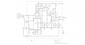
Barney Oliver's preamp (of HP) used the inductance of the cartridge in a very clever way as part of the eq. It won't work for moving coil types. See below.
Attachments
It's more complicated than that. With an MM, you can't ignore the inductance, and the load R in parallel with the load C also comes into play.
See RIAA Noise Calculator for an aid to calculating this stuff.
I'm a little lost here on the inductance. Only the resistive component of the inductance can generate thermal noise*. The load R is in parallel with the noise source reducing its effective resistance. The shunt C will attenuate high frequency noise generated but 500 pF won't have a lot of effect.
Maybe the series inductance will attenuate the noise if the load is low enough? I'm not sure it works that way. Even so the reactance is small compared to the load impedance.
*From Pg. 11 of Low Noise Electronic Design Motchenbacher and Fitchen, 1973.
"Dave Wilson believe 's the best at low voltage amplification"
a.wayne,
That would only point at one thing these days I imagine and that would be for MC phono stages. What I would really like to know is what is John doing today to further the field, not how to reuse something that he has done 40 years ago? Where is his thinking today. is there some new direction that he is trying to go or will he stand on his past accomplishments and just keep repackaging those same circuits?
There is also the question of whether the problem has been solved. There are many problems with very adequate solutions. They can be improved upon but sometimes there is no point. For example, I have a patent on an improved terminal clamp for a car battery. It works well and has benefits. Its also not practical in normal practice because its way more expensive to make, the easy on-easy off feature is not important etc. But it made for a very flashy car audio accessory. Most of the audio stuff we are finessing is in the premium battery clamp class. Interesting to a few but really an already solved problem. Like John I would use an old circuit that works, adapted to new parts if there is a reason. A new circuit is justified if it addresses a shortcoming identified in the older design.
I would like to find out what makes a discrete circuit better than an opamp of current high performance design. Otherwise its really hard to justify the effort making a discrete circuit with poorer measured performance than an opamp.
I'm a little lost here on the inductance.
The inductance reduces the shunting effect across the 47k load. The reactance is not small at HF since L is likely to be ~1H.
I would like to find out what makes a discrete circuit better than an opamp of current high performance design. Otherwise its really hard to justify the effort making a discrete circuit with poorer measured performance than an opamp.
Although it has been known for a while that many of the older popular RIAA equalization circuits placed too much of a current demand that was not met. It is not the same as the noise distortion trade off here.
Now in addition to using a current booster to handle feedback current demands the other approach JC uses is an open loop gain stage. Now as IC's are hard to operate open loop, Bruno Putzey's approach of lots of feedback especially at HF may be the IC optimum.
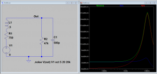
I went back and modeled the cartridge/input circuit to better understand what is happening.
The sim below explains it. The inductance of the cartridge isolates the shunt of the DCR from the input resistance allowing it to rise with frequency until the shunt cap starts bringing it down. This may be a real benefit of the Barney Oliver circuit since it has an active shunt working with the inductance. Possibly lower noise? Keith Johnson does something similar in his tape head preamp.
The sim below explains it. The inductance of the cartridge isolates the shunt of the DCR from the input resistance allowing it to rise with frequency until the shunt cap starts bringing it down. This may be a real benefit of the Barney Oliver circuit since it has an active shunt working with the inductance. Possibly lower noise? Keith Johnson does something similar in his tape head preamp.
Attachments
George,
Since you want to get ahead of the discussion, why don't you look up Harry Fletcher's research on how loud a broadband signal had to get to mask a tone. (I think he used 2,000 hertz at 10 db.)
This may help to explain why a non-harmonically related distortion can stand out so much.
Ed I don’t want to get ahead of anything.
")
Yesterday I went through Bell Labs archives for Harvey Fletcher’s auditory work there.
Bell System Technical Journal Search
There is a lot on single tone masker among other gems. I haven’t found something on masking by a broadband signal. Any link maybe?
This may be a real benefit of the Barney Oliver circuit since it has an active shunt working with the inductance. Possibly lower noise?
Demian
http://www.hparchive.com/Manuals/Barney_Oliver_Amplifier_Manual.pdf
The article describes (page 9 and page 14) the way to incorporate the resistance and inductance of the cartridge in the formation of the 2120Hz (75us) roll off point of the RIAA equalisation. I can't say if the L is used for lowering the noise too.
George
From A Different Era...
Dan.
Anybody know which manufacturers boosted vinyl highs ?.E. Phono Equalization Switch (-6 dB, RIAA,
+6 dB)
Below the INPUT selector control, and effective only in the PHONO position of that control,
a three-position slide switch allows some compensation for recording defects.
In the center (Normal) position, this switch provides the standard RIAA equalization.
In the left position, the high frequency response is dropped by 6 dB, while in the right position, the response is enhanced by 6 dB.
Some manufacturers (such as Deutsche Gramophone) conscientiously adhere to RIAA specifications, while others (names supplied on request)
enhance the high end to compensate for the deficiencies of the usual playback system.
If your speakers are flat, the -6 dB position will help correct this practice.
If you find the +6 dB position better in the majority of cases, your speakers (or your ears) need attention.
Dan.
Last edited:
George,
I just googled "noise masking Fletcher" and got a summary on the first item. But as cut and paste are iffy on my cell phone.
You do not have permission to vi I hope this gets you there.
But as you spent the effort, the answer is it to a noise level of 75 dB to mask the test tone. It was later that the Fletcher Munson curves were done so that he was only looking close to the most sensitive area.
So if we have 70 dB electrical s/n and can pick things out 64 dB below that allowing for 40 dB of EQ and 15 dB of spectrum drop, then SY and everyone else will be quite confused.
So I will make a simple point. Harmonically related 2nd and 3rd order distortion are masked at levels of around 30 dB down. Other noises are masked at 60 dB down when there is energy to mask them! Thus if you are playing a note at 50 hertz and there is a tone at 4138 hertz on a system with only 60 dB of s/n you may perceive it even if it is more than 100db down!
Of course this research was done in the 1930's and has been confirmed and refined many times since then!
I think it is time to stop this discussion as everyone seems to have snoozed off.
http://acousticslab.org/psychoacoustics/PMFiles/PMDownloads/Week4_Masking_Print.pdf
Second try!
Last edited:
SY and everyone else will be quite confused.
I can't answer for everyone else, but it's fairly clear to me what you left out. I assume it's the same for you and it's a deliberate trick.
Dan,
The quote function isn't working right but in simple terms if 2nd and 3rd are 30 dB down that's adequate. However 5th and higher should be 100 dB down. The useful bandwidth for noise calculations should be around 750 to 1000 hertz noise bandwidth. Or in very basic use multiply the nv/sqrt(hertz) by about 30. If that voltage is 1000 times the distortion voltage then it is buried by the noise. Or as simple as it gets if the actual noise voltage is 30 times the distortion you should be ok.
The quote function isn't working right but in simple terms if 2nd and 3rd are 30 dB down that's adequate. However 5th and higher should be 100 dB down. The useful bandwidth for noise calculations should be around 750 to 1000 hertz noise bandwidth. Or in very basic use multiply the nv/sqrt(hertz) by about 30. If that voltage is 1000 times the distortion voltage then it is buried by the noise. Or as simple as it gets if the actual noise voltage is 30 times the distortion you should be ok.
Last edited:
.
So if we have 70 dB electrical s/n and can pick things out 64 dB below that allowing for 40 dB of EQ and 15 dB of spectrum drop, then SY and everyone else will be quite confused.
So I will make a simple point. Harmonically related 2nd and 3rd order distortion are masked at levels of around 30 dB down. Other noises are masked at 60 dB down when there is energy to mask them! Thus if you are playing a note at 50 hertz and there is a tone at 4138 hertz on a system with only 60 dB of s/n you may perceive it even if it is more than 100db down!
Second try!
Ed, I no longer have any interest in this particular discussion, but I must say IN MY OPINION this numerology is unique to you.
I'm a little lost here on the inductance. Only the resistive component of the inductance can generate thermal noise*. The load R is in parallel with the noise source reducing its effective resistance. .
Simply take the real part of the net source impedance, works for any case. The National app note of 1977 goes through the math but leaves out the current noise of the op-amp. One nice thing about the Grado MI carts is that eliminating the source noise is fairly easy without any circuit tricks.
The logical conclusion here is that if we add more noise distortion doesn't matter!
No, the logical conclusion is that if the fundamental point is glossed over with a lot of extraneous activity, people will forget about it and concentrate on irrelevancies. I'm surprised no one has picked up on the major issue and called Ed on it- he has to be laughing.
Hint: what does the entire spectrum look like?
he National app note of 1977 goes through the math but leaves out the current noise of the op-amp.
It also leaves out the voltage noise. All they do (and my spreadsheet follows this) is to calculate the thermal noise at the input of an ideal (noiseless) amplifier. With that in hand, you can then go back and see the effects of en and in.
I am surprised that many here are thinking about phono input stages. The noise tradeoffs were addressed, and often analyzed, as far back as 40 years ago.
Is this some sort of mental 'exercise' that brings this up?
The irony, it burns!
- Status
- Not open for further replies.
- Home
- Member Areas
- The Lounge
- John Curl's Blowtorch preamplifier part II