Measuring some distortion with a mylar/polyester cap is not surprising. Whether it is audible depends on exactly how the cap is used in the circuit. With little or no signal voltage across it a cap cannot generate much distortion.simon7000 said:There is no way you can hear the difference between capacitors. Attached are my quick measuerments.
J.C.
As usual the peanut gallery is right. There is no way you can hear the difference between capacitors. Attached are my quick measuerments.
As usual pictures with no conditions, no schematics, no levels, no relation to any actual use. I prefer the way Samuel G. presents his data, one can actually use it.
Last edited:
For those of you who want to further learn about designing 'successful' audio equipment, I recommend searching the internet for lectures by Rupert Neve, who generally designs audio consoles.
I wish that I knew him personally, and I regret that 40 years ago, I turned down using a Neve Console and chose to make my own. At the time, I should have chosen the Neve, but I did not then know Rupert Neve's dedication to sound quality that was higher than the typical design engineer at the time.
I wish that I knew him personally, and I regret that 40 years ago, I turned down using a Neve Console and chose to make my own. At the time, I should have chosen the Neve, but I did not then know Rupert Neve's dedication to sound quality that was higher than the typical design engineer at the time.
..
I wish that I knew him personally, and I regret that 40 years ago, I turned down using a Neve Console and chose to make my own. At the time, I should have chosen the Neve, but I did not then know Rupert Neve's dedication to sound quality that was higher than the typical design engineer at the time.
Are you sure about that? Take a look at typical gain modules by him (his company?) from that era. Caps usually are tantalums or axial Philips types.
There's plenty of information about Neve electronics out there. They're sought after by musicians (and modern day fools
") ) because of sonic signature they have. They also get "cloned" en masse.
) because of sonic signature they have. They also get "cloned" en masse.And, by the way, putting modern caps in place of tantalums is taboo.
So, at the end of the day maybe it was good that you built your own..
Best,
Attachments
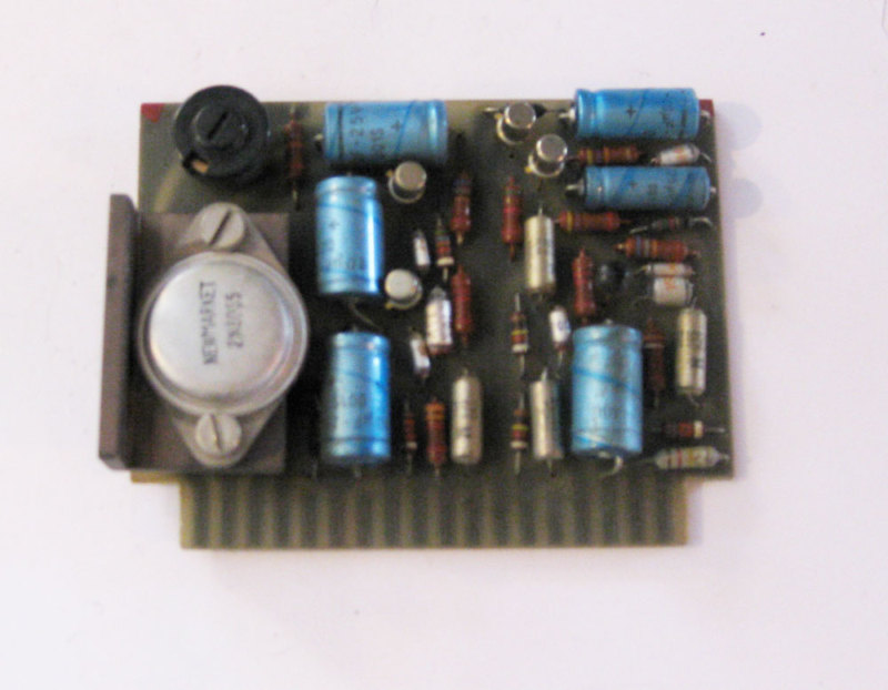
It's because they use capacitance to suchI have equal examples of designs that probably sound better than most IC based designs today.
advantage as to overcome the shortcomings
of capacitors !
A recipe for 'sound quality':
1) take a digital recording as a basis
2) record either empty groove noise or tape hiss, save A/D conversion of noise to digital sound file
3) make a stereo mix of (1) and (2)
4) add 'retro exciter' mastering tool, at a decent level
5) add a crosstalk between L and R channel, you need to worsen channel separation
As a result, you have a 'sound quality' of the analog of the seventies, quite indistinguishable.
It's because they use capacitance to such
advantage as to overcome the shortcomings
of capacitors !
A lot of polarized capacitors, all properly biased. Then a lot of band limiting at the input, good local decoupling and robust PSUs.
Not very different from the grandfather's modules
Vintage german modules (Neumann, Siemens, TAB, IRT, Lawo, ANT, Eckmiller, Adis, Monitora and Telefunken modules and Braunbuch scans)
Speaking of consoles and FETs, have a look on the posted schematics at Forssell site
forsselltech.com
George
Edit. Very true Pavel!
Your recipe will work any day.
Last edited:
Yes......There's plenty of information about Neve electronics out there. They're sought after by musicians (and modern day fools
Yes.So, at the end of the day maybe it was good that you built your own..
Dan.
No, they listened, but that is out of fassion.
I think you over generalize, musicians still choose fuzz pedals by listening only (there are literally dozens to choose from). NOS germanium pnp's are highly sought after for clones of many of the old circuits.
In my experience the folks more adamant about "listen only" are looking for obvious colorations and anything but accuracy.
As for the JFET modules, JFET's are far more robust to EMI and RFI, highly desireable in microphone/phono pre-amps.
Last edited:
jn, if you run two twisted pairs together along a path, where one might be an aggressor, what would be the optimum twisting and laying strategy to minimise any coupling: differing levels of twist, opposing twists, twisting of the two pairs with respect to each other, etc, ... ?
For two pair, the best strategies are distance and pitch ratio. Two pair with identical twist pitch or integer related ratio's will maximize coupling potential. Cat cables use 4 different pitches to reduce inter-pair coupling. Twist direction is not significant.
I agree, I'm not buying it. The ratios just have to be non integer related to retain magnetic orthogonality. I am unaware of any other criteria that would require all kinds of computer analysis..but what do I know??Its called CAT5, CAT6, CAT7 networking cable. The story is that AT&T used a big computer to calculate the optimum twist ratio and it took weeks of CPU time. I'm not sure I completely buy the story but the turns ratios on the 4 pair are very specific and tightly controlled to meet the crosstalk specs in the EIA-TIA standards.
Agreed. However, the twist pitch of the mains cable must not be integer related to the twist pitch of the signal cables if they are balanced pairs. Otherwise, the mains will be able to communicate it's magnetic field to the twisted pair.Common mode noise rejection.
JNs stuff has the mains cables in close proximity to the ICs to minimise the loop area, slightly different problems.
Simple coax cables won't couple.
BTW, at the phono level, I wouldn't recommend this technique. The impedance of the phono will rear an electric field coupling. There, I recommend twisting the grounding wire around the two phono cables very tightly, reducing the loop between the phono ground and the phono coaxes.
jn
A recipe for 'sound quality':
1) take a digital recording as a basis
2) record either empty groove noise or tape hiss, save A/D conversion of noise to digital sound file
3) make a stereo mix of (1) and (2)
4) add 'retro exciter' mastering tool, at a decent level
5) add a crosstalk between L and R channel, you need to worsen channel separation
As a result, you have a 'sound quality' of the analog of the seventies, quite indistinguishable.
Amen... and add a bit of wow and flutter and you're there. Listened to a Rega 3 the other day. Quite bad.
This week, I got two analog recorders up and running, after 20 years of storage. Need work now.

This week, I got two analog recorders up and running, after 20 years of storage. Need work now.
Must be getting harder to find the best tape. I see there is ATR, too bad they need to resort to the "feel good physics" to promote tape vs digital.
Last edited:
I have a question. I've seen several integrated amps (Onkyo, H/K, etc) that have switched power sockets on the case that you can plug your CD player or whatever into. Would using this be a better way to reduce the ground loop or does it increase noise? I suppose it would depend on implementation.
- Status
- Not open for further replies.
- Home
- Member Areas
- The Lounge
- John Curl's Blowtorch preamplifier part II