Scott your first line made me LOL "It's also the language of the "rapture of the nerds" at the singularity. Python is worth it, it's free and has a huge collection of well supported libraries. Google "Hello World in 7 min." They're right. It's become my goto for quick complex calculations with nice plots.
Let me qualify what I said last night. Bateman's results might have very well been fine for his discussion of RF de-stabalization of amps but is no help in separating phase (he throws it away) from real delay. Remember at HF the line has a real positive Z0 and it does not matter. He does not really explore or need to explore the LF implications. I am in the camp that this problem will yield to lumped element analysis, but am willing to do careful experiments to look at the other viewpoint.
It's also the language of the "rapture of the nerds" at the singularity" What a fabulious turn of a phrase.
Finishing off my treatise on my experience with loudspeakers. I might want to list a few things about loudspeakers that I learned over the years:
First, any speaker guru, while earnest and even brilliant, may be biased about his design, and will often dismiss or even actively suppress its problems.
Second, there are a number of 'laws of physics' tradeoffs that always make loudspeaker design almost impossible to get right. These include: Doppler distortion, horn throat distortion, mechanical resonances in speaker cabinets, quality and tolerance in building speaker drivers, (not all 12'' speakers are equal) as well as delay between drivers, xover problems, dispersion problems especially at high frequencies, etc.. EVEN honest measurements of speakers, that show most speakers fail in some way, are often avoided.
So, if you are into horns, you get efficiency, but terrible time delays near the cutoff and difficulty in getting multiple horns aligned. (the K-horn problem)
If you have a modest direct radiator speaker system, you WILL have Doppler distortion, even if the drivers are the best in the world.
Electrostatics and cheap woofers often have a 'throw' problem that pins their cones or panels to minimal movement without gross harmonic distortion.
ETC!
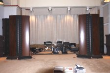
Now, for me the Wilson speaker cabinets are the heart of the whole series of Wilson Audio speakers. That is where Dave has put most of the money. They really are like 'talking rocks' rather than pleasantly resonant enclosures. This, to me, gives the most significant difference between them and many other direct radiator systems, and this is why I use them.
First, any speaker guru, while earnest and even brilliant, may be biased about his design, and will often dismiss or even actively suppress its problems.
Second, there are a number of 'laws of physics' tradeoffs that always make loudspeaker design almost impossible to get right. These include: Doppler distortion, horn throat distortion, mechanical resonances in speaker cabinets, quality and tolerance in building speaker drivers, (not all 12'' speakers are equal) as well as delay between drivers, xover problems, dispersion problems especially at high frequencies, etc.. EVEN honest measurements of speakers, that show most speakers fail in some way, are often avoided.
So, if you are into horns, you get efficiency, but terrible time delays near the cutoff and difficulty in getting multiple horns aligned. (the K-horn problem)
If you have a modest direct radiator speaker system, you WILL have Doppler distortion, even if the drivers are the best in the world.
Electrostatics and cheap woofers often have a 'throw' problem that pins their cones or panels to minimal movement without gross harmonic distortion.
ETC!
Now, for me the Wilson speaker cabinets are the heart of the whole series of Wilson Audio speakers. That is where Dave has put most of the money. They really are like 'talking rocks' rather than pleasantly resonant enclosures. This, to me, gives the most significant difference between them and many other direct radiator systems, and this is why I use them.
Last edited:
Scott your first line made me LOL "
It's also the language of the "rapture of the nerds" at the singularity" What a fabulious turn of a phrase.
If you follow Ray Kurzweil's singularity stuff you will end up with more laughs.
If you have a modest direct radiator speaker system, you WILL have Doppler distortion, even if the drivers are the best in the world.
Is there an immodest direct radiator without it?
Wavelength of 20kHz wave is 15km, and some are trying to argue with delays on 2m of wire .....
It is definitely a question of HF/VHF interference reflections only and their possible influence on amplifier stability. No low frequency 'smear' here.
Pavel
I think that jn makes a case not for a specific frequency but for the time difference that occur btn the LF and HF content of audio spectrum:
Using a matched impedance speaker line
And as you –correctly- highlight the HF issue with amplifying devices, you may notice that he does care for that:
A good example would be IC's. For the exact same geometry, a foamed dielectric running a permittivity of 1.05 vs a solid teflon running about 3, the characteristic impedance of the cable changes by a factor of 1/sqr(delta), roughly 1/1.7 or 60%. This material change will indeed modify the break frequency where return currents would start to concentrate in the source IC vs 50/50 shield path sharing. This alters the loop induction topology, frequency response, and external noise pickup sensitivity. Should the amp not have a well designed rail or primary supply topology (wire layout), this can alter the transfer function as a result of internal coupling.
Another example would be the permeability of the chassis, where ground loop current path would constrict earlier due to path reactance changes
jn
Is the low inductance sense resistor you fabricate for Scott like one of these two you described here?
George
I couldn't help myself.
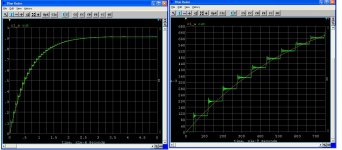
I entered Mr. Bateman's 200 unit simulation and compared the step response with the lumped equivalent of all 200 at the source. I used 10k as the frequency his 14 Ohm line and 1 Ohm load. Note, in general you can not do a simple transient response with frequency dependent components. Still this is sort of what I expected, kind of a conservation of energy thing.
In a funny way I think we are all agreeing, I'm just saying the Tline as a bulk component gives the same time constant/phase behavior.
Attachments
Low dispersion audio cables can be made by adding inductors. These may be necessary for lengths in the multi-km range, as telephone companies found after Heaviside did his theory. EM theory tells us that the lumped approximation is adequate for electrically small systems, where it is equivalent to the full wave theory in its predictions.gpapag said:I think that jn makes a case not for a specific frequency but for the time difference that occur btn the LF and HF content of audio spectrum:
If you have enough cone surface area, and the right xover frequencies, you can minimize Doppler to something reasonable.
3 and 4 way systems reduce this to a none issue IMO John, the issue with box speakers is getting enuff enclosure volume to not allow dynamic compression , even in the mid range area, some guys still use too small a mid driver enclosure..
After which you run into the limitation of your 1" tweeter, it's why i moved away from such setups when doing SOTA system, instead favoring line-source type speakers ...

a. Doppler is somewhat different than just harmonic or IM distortion, even though it comes out in a similar way. I can't comment on the mid driver enclosure volume. The WATT1 has a VERY SMALL enclosure volume, and it shows in the frequency response, but not in 'muddiness' that I normally associate Doppler with.
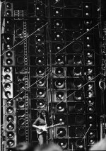
As I stated before, there are a series of tradeoffs, and you have to pick your choice. NOW, I listen at modest levels in a small apartment. Someone who listens at 'realistic' levels will most probably detect Doppler distortion from many speaker systems with limited cone area. As with the Grateful Dead, your solution of massed line source speakers might make sense.
As I stated before, there are a series of tradeoffs, and you have to pick your choice. NOW, I listen at modest levels in a small apartment. Someone who listens at 'realistic' levels will most probably detect Doppler distortion from many speaker systems with limited cone area. As with the Grateful Dead, your solution of massed line source speakers might make sense.
"Muddiness" is often due to lack of speaker stability, my earliest experiments focused on making modest bookshelfs very rigidly locked into place - I then found listening to demos of speaker of the Wilson 'calibre' quite laughable, the 'wooliness' of the sound meant that 95% of the speaker's worth was going straight down the plughole ...The WATT1 has a VERY SMALL enclosure volume, and it shows in the frequency response, but not in 'muddiness' that I normally associate Doppler with.
As I stated before, there are a series of tradeoffs, and you have to pick your choice. NOW, I listen at modest levels in a small apartment. Someone who listens at 'realistic' levels will most probably detect Doppler distortion from many speaker systems with limited cone area.
Realistic levels being done right is all about the amplifier working well - I've repeated this 'experiment' literally thousands of times and never had the speaker not easily do the job. Of course, listening to conventional setups, which get into trouble at very modest listening levels, makes it understandable that people point to an obvious villain - the speaker ...
In a funny way I think we are all agreeing, I'm just saying the Tline as a bulk component gives the same time constant/phase behavior.
http://i.cmpnet.com/rfdesignline/2010/06/C0580Pt1edited.pdf
http://i.cmpnet.com/rfdesignline/2010/06/C0580Pt2edited.pdf
http://i.cmpnet.com/rfdesignline/2010/06/C0580Pt3edited.pdf
Bob Peace on a ‘Precision (current sense) resistor’
") :
:Bob Pease: His last challenge, Part three--The precision resistor | EDN
George
http://i.cmpnet.com/rfdesignline/2010/06/C0580Pt1edited.pdf
http://i.cmpnet.com/rfdesignline/2010/06/C0580Pt2edited.pdf
http://i.cmpnet.com/rfdesignline/2010/06/C0580Pt3edited.pdf
Bob Peace on a ‘Precision (current sense) resistor’
Bob Pease: His last challenge, Part three--The precision resistor | EDN
George
Great thanks, one of the CAD guys at work suggested this workaround but left all the work up to me. I think I've spent enough time on this for a while.
I think I've spent enough time on this for a while.
I thought it is a good match for your script writing interests / TL investigations.
Roy McCammon,the author of these models is a long-time TL fiddler. I had read an earlier article from him where P1, P2 blocks of Fig.2 were considered as delay line functions only.
Here are comments for his later TL model by people you know
Ott, Gilbert, Sauer, Harvey, and Fong discuss the new Spice model for transmission lines | EDN
If a fast pulse generator is available, you may check this (note para 2.3)
http://www.scielo.br/pdf/rbef/v29n3/a08v29n3.pdf
As we are on impedance measurement mode and you have a lot of eight leg animals, see here (Fig.2) a way to measure the impedance profile of a grounded load. A low inductance cvr is still required.
http://www.analog.com/static/imported-files/application_notes/AN-847.pdf
George
Last edited:
I thought it is a good match for your script writing interests / TL investigations.
Roy McCammon,the author of these models is a long-time TL fiddler. I had read an earlier article from him where P1, P2 blocks of Fig.2 were considered as delay line functions only.
Here are comments for his later TL model by people you know
Ott, Gilbert, Sauer, Harvey, and Fong discuss the new Spice model for transmission lines | EDN
Thanks again George, I will go no further without giving this model a try.
From part 3...
Does the model work at DC? It is not obvious from the unfamiliar forms that the solution takes. The characteristic impedance is very high. How, one might ask, can one get any signal into the transmission line at all? The answer is that the line is mismatched at both ends and the reflections from the far end diminish the impedance at the near end and the reflections at the near end diminish the impedance at the far end. The two ends swap geometrically decreasing reflections that, with a little smoothing, look just like an RC-charging curve. The derivation and solution of the Telegrapher's Equations makes no assumption about the frequency of the signals and does not exclude DC. It ought to work. And in fact it does.
With all that has been brought up showing the complexity of transmission line equations, it must be remembered that it is still only a MODEL, most of which was derived even before they discovered electrons, much less, quantum mechanics.
More advanced textbooks add the quantum mechanical aspects to current flow, and this further complicates the situation and infers the subtle nuances that our ears seem to detect in differences between connecting wires, due to geometry, or material properties of both the insulator or the conductor.
More advanced textbooks add the quantum mechanical aspects to current flow, and this further complicates the situation and infers the subtle nuances that our ears seem to detect in differences between connecting wires, due to geometry, or material properties of both the insulator or the conductor.
Last edited:
- Status
- Not open for further replies.
- Home
- Member Areas
- The Lounge
- John Curl's Blowtorch preamplifier part II