ps...you need a low inductance cvr?
jn
On a lark I found a mint pair of Dahlquist DQ10's for very short money so I will try the imaging experiment. On some LP's they could give scarey good images. If I could borrow a cvr that would help, in return I have a very deep "junk" box of IC's.
On a lark I found a mint pair of Dahlquist DQ10's for very short money so I will try the imaging experiment. On some LP's they could give scarey good images. If I could borrow a cvr that would help, in return I have a very deep "junk" box of IC's.
Join the Fray , on the dark side ............

Last edited:
On a lark I found a mint pair of Dahlquist DQ10's for very short money so I will try the imaging experiment. On some LP's they could give scarey good images. If I could borrow a cvr that would help, in return I have a very deep "junk" box of IC's.
When you change wire, do you use the same length or same resistance?
I have an all new power amp that I have to evaluate. I need speakers of 'Sasha' quality to effectively evaluate them. My Met 7's are fine for general listening, but they just are not 'revealing' enough.
"Quality" in this case means some overly priced speakers that have ridiculously low impedance and a non smooth frequency response, hardly "quality"

On a lark I found a mint pair of Dahlquist DQ10's for very short money so I will try the imaging experiment. On some LP's they could give scarey good images. If I could borrow a cvr that would help, in return I have a very deep "junk" box of IC's.
I heard a Dahlquist set up in the early 80's and I have never forgotten it. Stunning.
I have found that this 'series' of loudspeakers from the WATT1 to the Sasha works for me to reveal the subtle details that make differences in audio electronics most easily audible.
Another way is direct driven electrostatic microphones, which I also sometimes use.
An excellent counter-example is the Sequerra Met7. I got them cheap! And I have used them 10 times more than the WATT's over the years. They do OK, but they are 'forgiving' and that makes them difficult to use for serious evaluation of other components.
Without acoustic reproduces of similar quality to the WATT's or the STAX headphones, I can understand why many here don't bother much with subtle differences in audio electronics.
JN,
I like your cable test. A question related to the audio relevance, that is, real world speakers. In order to achieve the optimum settling time, wouldn't the cable need to follow the complex impedance of the load?
That'll be my cable!
Yes, it should. What are the chances of doing that?
I recommend putting the line z as close to the middle of the speaker z range as possible. And to make it easier, you really don't have to worry about bass frequencies being delayed by 10 microseconds, no? Same kinda applies to the highs, as we lose ITD resolution, but I suspect keep IID, so it may pay to consider the hf z of the load.
My edumacated guess is to worry only from about 500 hz up. As I said before, a zip is roughly 100 ohms hf, paralleling 8 twisted pieces of a #18 for example, drops that to 12.5 ohms hf, or roughly 35 to 50 ohms audio.
On a lark I found a mint pair of Dahlquist DQ10's for very short money so I will try the imaging experiment. On some LP's they could give scarey good images. If I could borrow a cvr that would help, in return I have a very deep "junk" box of IC's.
No problemo. I've a 100 milliohm one in the woiks as we speak. I'll finish it, attach some wires, and send it off to you. It's made using single sided perf, so I can't plane down one side to embed it into an aluminum case for heatsinking. That limits the current you can drive, I just have no idea what that is in free air.
It's 40 1 ohm resistors in a series parallel combo, two 50 milliohm composite resistors interleaved magnetically antiparallel to reduce self inductance.
Whatever you do, don't lend it to a physicist who owns a 20 ampere power supply, he'll toast it.
It uses about ten cents worth of materials, so shipping it back would be out of the question..
jn
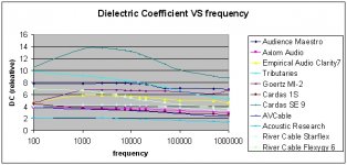
Something I did for Gene D at AH.. It uses data he measured. I cannot vouch for the absolute accuracy of the data, but it seemed ok.Years ago, I tried the formula to estimate the L of some cables but I failed miserably due to the field spread of these constructions (I didn’t know that then but I suspected it). George
jn
Attachments
It's 40 1 ohm resistors in a series parallel combo, two 50 milliohm composite resistors interleaved magnetically antiparallel to reduce self inductance.
Whatever you do, don't lend it to a physicist who owns a 20 ampere power supply, he'll toast it.
It uses about ten cents worth of materials, so shipping it back would be out of the question..
jn
OK sounds like a plan. Started reading Bateman, his biggest concern seems to be high frequency amp stability. I'll check again but the low frequency photos are with his complicated speaker simulated load (jez he'a a horn man I figure the IAD stuff would be lost on him).
On your figure of yesterday, for discussion sake take the degenerate cases of open and shorted load and just for a second consider them as just bulk L or C. The current and voltage are either plus or minus pi/2 in phase. I hope this 90 degrees of phase is not interpreted as delay.
Without acoustic reproduces of similar quality to the WATT's or the STAX headphones, I can understand why many here don't bother much with subtle differences in audio electronics.
uhhhh yeah wattever
OK sounds like a plan. Started reading Bateman, his biggest concern seems to be high frequency amp stability. I'll check again but the low frequency photos are with his complicated speaker simulated load (jez he'a a horn man I figure the IAD stuff would be lost on him).
I vaguely recall figure 5, a scope photo, but honestly, I last looked at it quite a while ago. He does indeed look to be hf stability concerned. Note that in order to sim a cable accurately enough to look like reality, he needed 200 plus stages of L/C.
Not on purpose..On your figure of yesterday, for discussion sake take the degenerate cases of open and shorted load and just for a second consider them as just bulk L or C. The current and voltage are either plus or minus pi/2 in phase. I hope this 90 degrees of phase is not interpreted as delay.
For load < line, the test views how quickly the line current rises to that which the output voltage step wishes to load to react to. That is a simple stepped exponentially decaying rise as per my earlier graph.
For Load > line, it is more complex to visualize as the reflection is positive at the load but negative at the source... a step voltage from the amp will cause a step current at the cvr, which will then oscillate around the final current value, the amplitude of the oscillation will decay exponentially to zero.
As to your phase question, a very reasonable and I believe, and accurate one...my graph is indeed absoluting the value for load > line. I've made no distinction between settling up to final value, and settling down to final value, perhaps that should be the case. Nice call.
jn
Last edited:
I realize that I don't refer much to my experience with loudspeaker design, but that is what I first started with, more than 50 years ago.
I was asked by a former high school buddy to make a sound system for a Coffee House, that was all the rage at that time, amplifying voices for folk music groups.
The sound system could be simple, but hopefully good enough to not interfere with the live performances. Of course, there was not much money available, but there was a Bogen PA amp/mixer that was perfect for the job at hand.
I, at the time, had three years of college, now emphasizing physics, under my belt, and a year at UL as a tech, so I knew my way around a little. I also had some textbooks on audio reproduction that I had read cover to cover. They were actually pretty good.
So I decided that the best that I could do was to build a large infinite baffle with a single 'full range' loudspeaker. There were a number of products available, but I was stuck with an EV $40, 12" speaker with a 'wizzer cone' to work with. Actually, it was not that bad, but then I had to make the enclosure.
I was able to make a real 'infinite baffle' loudspeaker with just a large sheet of Celotex with the speaker mounted on, mounted on an upper corner of the room that we were using, then stuffing the back lots of fibreglas. It wound up working pretty well, for what it was, and that was my start as an audio 'consultant'. (more later)
For my apartment system, I got an AR-1, 2 way speaker (12'' cone woofer, and 8" midrange) that came in as a trade at the local hi fi store. I also got a Dyna Mk3, and a Dyna preamp from the same source. It seems that 'everybody' even then (1963) was trading in their tubes and mono amps for solid state stereo.
I then played with damping factor, AND found that my AR-1 indeed did sound better with a damping factor of 1, rather than 15 as presented by the Dyna. Fascinating!
In any case, I started to make my first 'reference' mono audio system that I could learn from. For stereo reproduction, I later got a pair of Koss pro-4 headphones that sounded amazingly accurate at the time. (more later)
Last edited:
- Status
- Not open for further replies.
- Home
- Member Areas
- The Lounge
- John Curl's Blowtorch preamplifier part II